Modern enterprise networks are moving more traffic than ever—cloud applications, video collaboration, AI workloads, and storage replication all push bandwidth and latency requirements beyond what copper cabling can comfortably handle over longer distances. At the same time, data centers and campus networks are becoming more modular: switches, routers, and NICs are expected to scale port-by-port without forcing a full hardware refresh whenever speeds or cabling standards change.
That’s where fiber connectivity becomes the practical backbone for high-speed links. But network equipment doesn’t “speak fiber” by itself—the electrical signals on a switch ASIC or a server NIC must be converted into optical signals that can travel through fiber, and then converted back again on the other end. A fiber transceiver is the pluggable interface module that performs this conversion, enabling Ethernet devices to use different fiber types, reach different distances, and upgrade link speeds with minimal disruption.
🔅 What Is A Fiber Transceiver
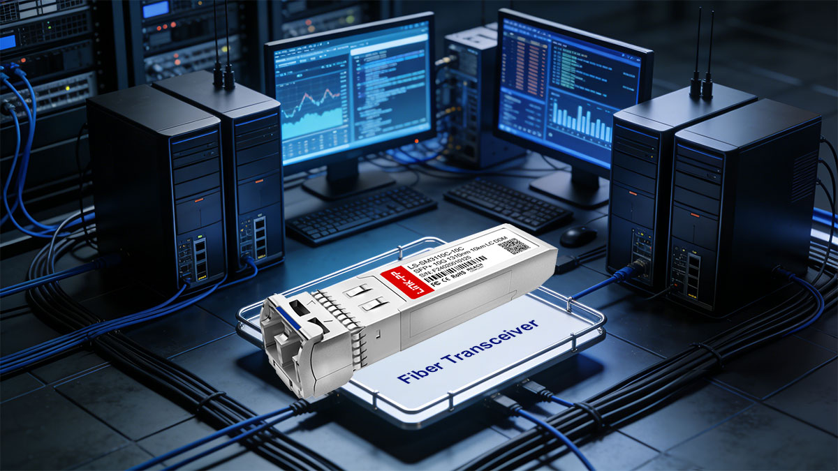
A fiber transceiver is a compact, hot-pluggable module that converts electrical Ethernet signals into optical signals for transmission over fiber, and converts incoming optical signals back into electrical data for the host device. In practice, it acts as the “last-mile” optical interface on switches, routers, and network interface cards, determining key link characteristics such as speed, wavelength, connector type, and reachable distance.
Basic of Fiber Optic Technology
Fiber optic communication works by sending data as pulses of light through a glass (or sometimes plastic) strand rather than as electrical current through metal. Light is guided down the fiber core by total internal reflection, and the transmission behavior is strongly affected by the fiber’s core diameter and refractive index profile. This is why multimode fiber (MMF)—with a larger core—supports multiple light paths (modes) and is typically used for shorter distances, while single mode fiber (SMF)—with a much smaller core—supports a single propagation mode and is optimized for longer distances and higher signal integrity.
Two practical details matter significantly in real-world deployments: wavelength and loss/dispersion. Common Ethernet optics use 850nm for MMF (typically paired with the VCSEL laser) and 1310nm or 1550nm for SMF (often paired with the DFB laser). As distance increases, the link budget must account for attenuation from fiber length (e.g., dB per km), connector and splice losses, and signal degradation from dispersion. This is why the “same speed” module may exist in multiple variants—because the optical physics and fiber characteristics define what distances are realistic and stable.
Role of Fiber Transceiver in Ethernet Networks
In an Ethernet system, the switch or NIC handles packet processing, but it outputs data as high-speed electrical lanes that can’t be launched directly into fiber. A fiber transceiver sits at the port and provides the PHY-side optical interface: it takes the host’s electrical serial data (often via SERDES lanes), drives an internal laser to generate a modulated optical signal, and then receives light on the opposite direction using a photodiode and amplifier chain to reconstruct the electrical signal. This conversion is not only about “turning electricity into light”—it must meet strict Ethernet requirements for signal integrity, timing, and error performance at the specified data rate.
Just as importantly, the transceiver defines how the link is built and maintained operationally. It exposes identification and diagnostics to the host (commonly via an I²C-based management interface), allowing network teams to verify module type, supported speed, wavelength, and sometimes real-time metrics like transmit power and receive power. It also determines the physical connectivity details—such as whether the port uses LC duplex, supports BiDi simplex, or requires a specific fiber grade (e.g., OM3/OM4 vs OS2). In short, the transceiver is the interchangeable component that lets the same switch platform connect to different media types and distances without redesigning the base hardware.
🔅 How Does A Fiber Transceiver Work
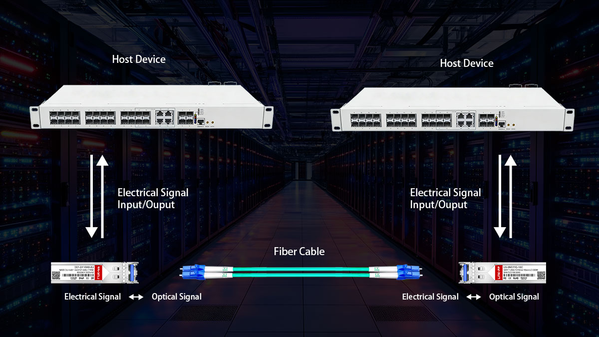
A fiber transceiver (optical module) works as a bidirectional bridge between electrical signals inside network equipment and optical signals traveling through fiber. In simple terms, it converts “electrical ↔ optical”, enabling high-speed, low-loss transmission over short or long distances.
Internal Structure of A Fiber Transceiver
Inside a fiber transceiver, the design is built around two main paths: a transmit (Tx) channel that turns electrical data into light, and a receive (Rx) channel that turns incoming light back into electrical data. Supporting these are control/monitoring circuits (often via I²C), power conditioning, and an optical interface (connectors, lenses, and alignment structures) to couple light efficiently into the fiber.
The table below summarizes the key internal components and explains what each one does within the transmit and receive paths.
| Key Components |
Main Function |
| Transmitter Optical Sub-Assembly (TOSA) |
Converts the electrical drive signal into optical output; typically includes a laser/LED, optical isolators (in some designs), and coupling optics. |
| Laser Diode |
The light source for transmission: VCSEL is common for short-range multimode (e.g., 850nm), while DFB/FP lasers are common for longer-range single-mode (e.g., 1310/1550nm). |
| Laser Driver |
Amplifies and shapes the outgoing electrical data to properly modulate the light source, controlling swing, bias, and modulation current. |
| Receiver Optical Sub-Assembly (ROSA) |
Captures incoming light and converts it into an electrical signal; typically includes a photodiode and optical coupling structures. |
| Photodiode |
Converts received optical power into an electrical current; APD may be used for higher sensitivity in longer links. |
| Transimpedance Amplifier (TIA) |
Converts tiny photodiode current into a usable voltage signal and provides initial low-noise amplification. |
| MCU/EEPROM (DDM/DOM Interface) |
Stores module ID and parameters, and reports diagnostics such as Tx/Rx power, temperature, voltage, and bias current to the host device. |
| Limiting Amplifier / CDR (optional) |
Restores signal amplitude (limiting amp) and may recover clock/data (CDR) for higher-rate modules to reduce jitter and improve signal quality. |
| Connector Interface (LC, SC, etc.) |
Physically links the transceiver to the fiber cable, ensuring alignment and low insertion loss. |
Each component plays a vital role in maintaining high signal quality, ensuring synchronization between transmitting and receiving ends, and supporting consistent optical performance across various network conditions.
Working Principle of Fiber Transceivers
The fiber transceiver operates in two stages: converting electrical signals into modulated light for transmission, and converting received light back into electrical signals for the host. Below is a clear breakdown of what happens in the transmit (Tx) path and the receive (Rx) path.
Transmit Process (Tx)
The host device (switch/NIC) sends a high-speed electrical data stream into the transceiver’s Tx side. The laser driver conditions this signal (setting bias/modulation) and drives the laser/VCSEL/LED in the TOSA so the light output is modulated to represent digital “1s and 0s.” The resulting optical signal is coupled through internal optics to the connector and launched into the fiber, where it travels with low attenuation to the far end.
Receive Process (Rx)
Light arriving from the fiber enters the module through the optical interface and is directed into the ROSA. The photodiode converts the optical signal into a very small electrical current, which is then amplified and converted into voltage by the TIA. Depending on the module type and data rate, a limiting amplifier and/or CDR may further reshape the waveform and recover timing before outputting a clean electrical signal back to the host device, completing the “optical-to-electrical” conversion for Ethernet processing.
🔅 Key Parameters of A Fiber Transceiver
Key parameters define a fiber transceiver's performance and compatibility. Understanding these specs ensures optimal network operation and prevents mismatches.
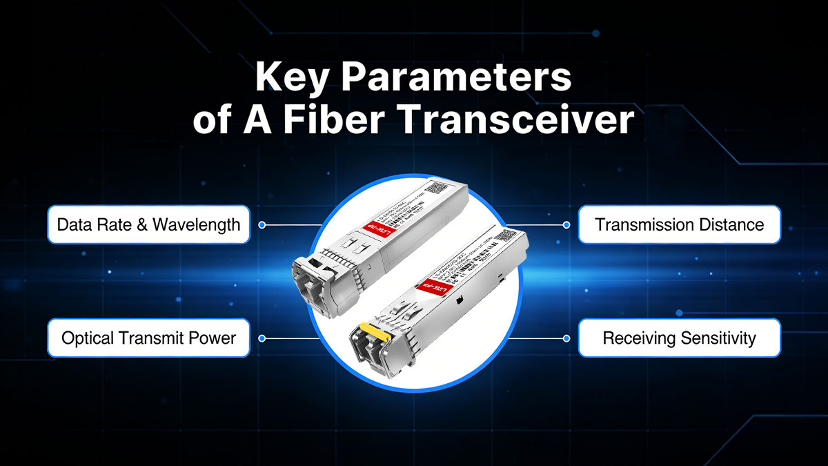
Data Rate & Wavelength
The data rate refers to the speed at which a transceiver can send data, typically ranging from 1G to 800G. The wavelength defines the light’s frequency, with common options being 850nm (for short-range) and 1310nm/1550nm (for long-range) wavelengths.
Transmission Distance
Transmission distance depends on the fiber type and the data rate. Single-mode fibers allow longer distances (up to 80km or more), while multimode fibers are suited for shorter distances, typically up to 550m for high data rates.
Optical Transmit Power
Optical transmit power is the strength of the light signal emitted from the transceiver. This power typically ranges from -9dBm to +5dBm, with higher power required for longer distances or higher-performance applications to maintain signal integrity.
Receiving Sensitivity
Receiving sensitivity refers to the minimum optical power level required for the transceiver to correctly receive and decode the incoming signal. This value typically ranges from -25dBm to -9dBm, and lower sensitivity is better for longer distance or weaker signal conditions.
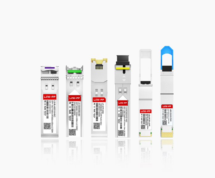
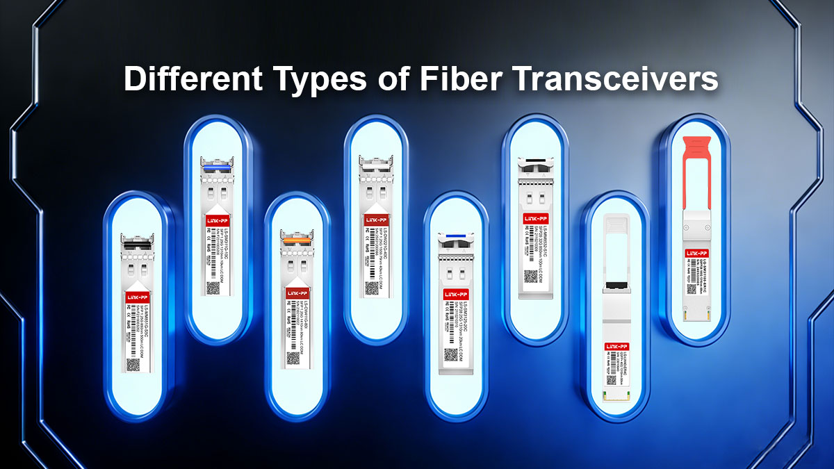
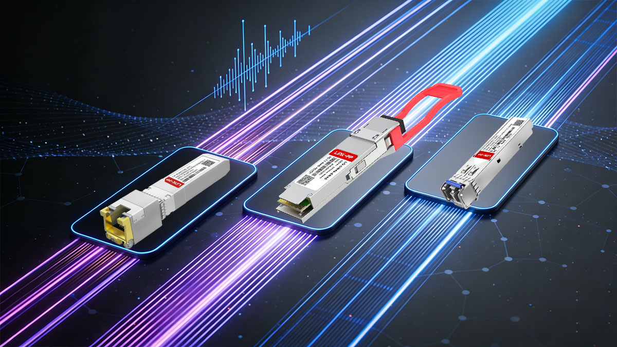
🔅 Different Types of Fiber Transceiver
Fiber transceivers come in multiple types because networks vary in fiber media, distance, bandwidth, and port density. Understanding the common categories below helps you quickly narrow down the right module for your network application and budget.
Single Mode vs. Multimode Fiber Transceiver
Single-mode and multimode fiber transceivers differ mainly in how light propagates through the fiber core, which directly impacts reach, tolerance to dispersion, and typical deployment scenarios.
Single mode fiber transceivers couple light into a very small core to minimize modal dispersion, making them the default choice for long uplinks (campus/metro) and higher-distance budgets, while multimode fiber transceivers launch light into a larger core to support cost-effective short links within data centers or buildings, where runs are limited and connectors are plentiful.
In practice, your decision usually comes down to existing cabling (OS vs. OM grades), required distance at the target data rate, and total link budget, since using the wrong fiber type can sharply reduce achievable reach or require redesign. The table below highlights the most important differences to help you choose quickly.
| Feature |
Single Mode Fiber Transceiver |
Multimode Fiber Transceiver |
| Fiber Cabling |
OS1/OS2 |
OM1/OM2/OM3/OM4/OM5 |
| Common Wavelength |
1310nm/1550nm |
850nm |
| Typical Transmission Distance |
Up to 80km |
Up to 550m |
| Best for |
Campus, metro, long uplinks |
Data centers, short interconnects |
| Cost |
Higher |
Lower |
CWDM vs. DWDM Fiber Transceiver
CWDM and DWDM fiber transceivers both use WDM (wavelength-division multiplexing) to send multiple optical channels over a single fiber, but they target very different capacity and design goals.
CWDM fiber transceiver uses wider wavelength spacing, which relaxes laser stability requirements and often enables more cost-effective, simpler deployments for enterprise or campus links where channel count is modest and ultra-long reach is not the priority. DWDM fiber transceiver uses much tighter spacing, allowing significantly higher channel density and better scalability for high-capacity transport; it typically relies on more precise optics and tighter control of wavelength accuracy, which is why it’s common in metro/carrier environments and engineered backbone links.
The following table compares CWDM and DWDM across the key differences.
| Feature |
CWDM Fiber Transceiver |
DWDM Fiber Transceiver |
| Channel Spacing |
20nm (transport up to 18 CWDM wavelengths) |
0.8nm/0.4nm (carry 40, 80, or up to 160 wavelengths) |
| Modulation Laser |
Uncooled Laser (electronic tuning) |
Cooling Laser (temperature tuning) |
| Application |
Metropolitan area networks and access networks |
Large-scale enterprise networks and data center interconnects |
| Cost |
Lower |
Higher |
SFP vs. SFP+ vs. SFP28 Fiber Transceiver
SFP, SFP+, and SFP28 share the same compact form factor, but they are built for different electrical signaling speeds and therefore have different requirements for host ports, signal integrity, and supported standards.
SFP fiber transceiver is typically used for 1G links and is common in access or legacy uplinks; SFP+ fiber module targets 10G and is widely deployed for server-to-switch and switch uplinks; SFP28 transceiver supports 25G, delivering higher bandwidth per port and is often chosen for modern leaf–spine designs where 25G server connections and 100G uplinks are common.
The table below summarizes the practical differences among SFP, SFP+, and SFP28.
| Feature |
SFP |
SFP+ |
SFP28 |
| Typical Data Rate |
1G |
10G |
25G |
| Fiber Type |
OM1/OM2/OS1/OS2 |
OM3/OM4/OS1/OS2 |
OM3/OM4/OS1/OS2 |
| Connector |
LC/SC/RJ-45 |
LC/RJ-45 |
LC |
| DOM Support |
Yes or No |
Yes |
Yes |
| Standard |
SFP MSA |
IEE802.3ae |
IEEE 802.3by |
| Cost |
Lower |
Medium |
Higher |
QSFP+ vs. QSFP28 Fiber Transceiver
QSFP+ and QSFP28 use a similar high-density form factor, but they differ in lane speed and total bandwidth, which affects how you design uplinks and breakouts.
The QSFP+ transceiver is most commonly used for 40G (typically 4×10G lanes), fitting older aggregation layers and 40G fabrics, while the QSFP28 transceiver is designed for 100G (typically 4×25G lanes), making it the mainstream choice for modern spine/leaf backbones and higher-capacity uplinks.
In practice, selection depends on your switch/NIC port capability, whether you need breakout links (e.g., 40G→4×10G or 100G→4×25G), and the optics standard you plan to run (SR/LR/ER and beyond). To help you choose quickly, the table lists the practical distinctions between QSFP+ and QSFP28.
| Feature |
QSFP+ |
QSFP28 |
| Typical Data Rate |
40G |
100G |
| Lane Configuration |
Four 10Gbps lanes |
Four 25Gbps lanes |
| Connector |
LC/MTP/MPO-12 |
LC/MTP/MPO-12 |
| Standard |
IEEE 802.3ba |
IEEE 802.3bm |
| Use Case |
Moderate-speed data center and enterprise network |
High-density, high-speed network connections |
| Cost |
Lower |
Higher |
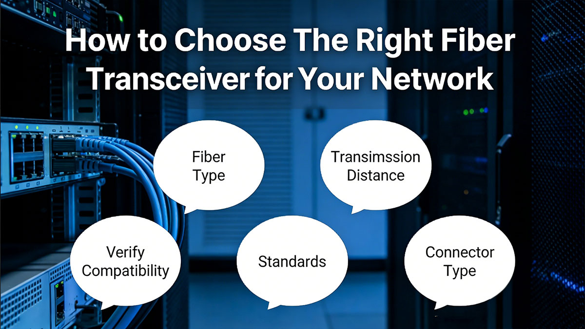
🔅 How to Choose The Right Fiber Transceiver for Your Network
Choosing the right fiber transceiver is mainly about aligning the module with your port capabilities and your physical link requirements. This prevents common failures like link-down issues, unexpected distance limits, or mismatch between optics, fiber, and connectors.
Match the Transceiver to Your Switch or NIC Requirements
Start from the host port: confirm the form factor (SFP/SFP28/QSFP28), supported speeds, and whether the port expects the optical or copper module. Then match the required Ethernet/PHY standard (for example, 10GBASE-SR vs. 10GBASE-LR) and check if your platform enforces vendor coding or requires a specific firmware revision.
Choose the Right Fiber Type and Transmission Distance
Select optics based on your installed cabling and measured span length. Use multimode SR modules with OM3/OM4 for short runs inside a rack/room; use single-mode LR/ER/ZR modules with OS2 when distance exceeds multimode limits or when future expansion is likely. Always validate distance at the target data rate, not “typical” reach.
Consider Wavelength, Connector Type, and Link Budget
Confirm the wavelength plan end-to-end: 850nm for most SR multimode fiber transceivers, 1310nm/1550nm for single-mode fiber transceivers, and consistent CWDM/DWDM channels if WDM is used. Match the connector type (LC, MPO/MTP) and polarity for duplex or parallel optics. Calculate link budget: Tx power − total loss (fiber + connectors + splices) must stay above receiver sensitivity with margin.
Verify Compatibility, Standards, and Vendor Support
Check the fiber transceiver’s compliance with relevant MSA/IEEE specs and confirm the exact part is qualified on your switch/NIC model. If mixing vendors, ensure DOM/DDM reporting, alarms, and EEPROM ID fields are recognized by the host OS. For live deployments, prioritize modules with clear warranty terms, traceable test reports, and responsive support.
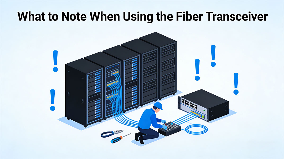
🔅 What to Note When Using the Fiber Transceiver
Most fiber transceiver problems in the field come from handling, contamination, or preventable link-loss issues rather than the optics themselves. The practices below focus on protecting the module’s electronics and keeping the optical path stable so the link stays clean and predictable.
Prevent Electrostatic Discharge (ESD) Damage
Treat every transceiver module as ESD-sensitive from the moment it leaves the bag. Wear a grounded wrist strap, handle the transceiver by the housing (not the circuitry), and install it only at an ESD-safe workstation when possible. Avoid placing modules on plastic surfaces; use an anti-static mat or the original conductive packaging.
Keep the Optical Interface Clean at All Times
Contamination on the end-face is a top cause of high loss and intermittent errors. Keep dust caps on whenever a module or patch cord is unplugged, and never leave an LC/MPO port exposed on an active panel. If you suspect contamination, inspect/clean first—“wipe and hope” can grind debris into the ferrule and make loss worse.
Avoid Touching the Gold Finger Contacts
Finger oils and residue increase contact resistance and can cause unstable recognition or random link flaps. Hold the module by its sides or bale latch, and avoid sliding the contacts across metal surfaces. If contamination occurs, clean only with appropriate electronics-grade swabs and solvent, then allow full drying before reinsertion.
Do Not Frequently Plug and Unplug Transceiver Modules
Repeated insertion cycles wear the cage/connector interface and can loosen alignment, especially in high-density ports. Hot-plugging also increases the chance of ESD events and transient link instability. If troubleshooting, swap with a known-good module only after checking fiber polarity, cleaning connectors, and confirming the port configuration.
Monitor Fiber Link Attenuation and Signal Loss
Use DOM/DDM readings (transmitter power, receiver power, operating temperature, supply voltage, laser bias current) to spot degradation early—an Rx power trend dropping over days/weeks often indicates dirty connectors, micro-bends, or a stressed patch cord. Compare measured Rx power against the module’s specified sensitivity and your link budget margin. When values approach thresholds, clean/inspect and re-test before failures occur.
🔅 Frequently Asked Questions about Fiber Transceiver
What types of fiber transceiver form factors are available?
Common form factors for fiber transceivers include SFP , SFP+, SFP28, QSFP+, QSFP28, and QSFP-DD. Each varies by data rate, size, and port density, and the choice depends on your switch/NIC requirements and desired bandwidth.
How do 1310nm and 850nm fiber transceivers differ?
1310nm fiber transceivers are used for single-mode fibers and provide longer distance capabilities (up to 40+ km), while 850nm fiber transceivers are commonly used for multimode fibers, supporting shorter ranges (up to 550m) but offering higher bandwidth on shorter links.
Can I use single mode with a multimode fiber transceiver?
No, single mode and multimode fiber transceivers are incompatible with each other because they use different core diameters and light propagation methods. Using them together will lead to high loss and signal failure, as the light from the transceiver will not properly propagate through the fiber.
Does a fiber transceiver support both duplex and simplex communication?
Yes, some fiber transceivers support both duplex (two-way communication on separate fibers) and simplex (one-way communication) depending on the module's configuration and the type of fiber used. This is typically determined by the connector type and how the network is structured.
How to clean a fiber transceiver?
To clean a fiber transceiver, use a fiber optic cleaning kit that includes lint-free wipes and alcohol or a cleaning swab specifically designed for the connectors. Always clean the transceiver’s optical interface gently to avoid damaging the ferrule or introducing contaminants.
🔅 Conclusion
Fiber transceivers are essential components for modern networks, converting electrical signals into optical signals for transmission over fiber and vice versa. Understanding their key parameters, such as data rate, wavelength, transmission distance, and compatibility with various network components, is crucial for ensuring reliable, high-performance connections. Whether it's selecting the right fiber type, ensuring proper form factor compatibility, or factoring in wavelength and connector types, choosing the right fiber transceiver can prevent issues such as signal loss, misalignment, or link failures.
To find the perfect fiber transceiver for your network, consider the specific needs of your equipment and deployment scenario. Whether you're upgrading your data center, setting up a campus network, or expanding your infrastructure, the LINK-PP Official Store offers a wide range of high-quality fiber transceivers to meet your requirements. Explore our optic fiber transceivers to optimize your network performance and scalability.