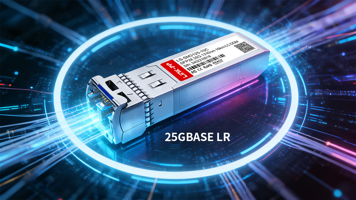
25GBASE LR is the standard choice for 25G single-mode connections up to 10km, making it a critical optical interface in modern data center and enterprise backbone deployments. As networks migrate from 10G to 25G to increase port density and reduce cost per bit, selecting the right 25GBASE-LR SFP28 module directly affects link stability, compatibility, and long-term operational efficiency.
Unlike short-reach SR optics designed for multimode fiber, 25GBASE LR operates at 1310nm over single-mode fiber, enabling longer campus, metro-access, and cross-building connections without complex DWDM systems. However, procurement decisions should not rely on distance alone. Power consumption, link budget, fiber type, switch compatibility, compliance standards, and lifecycle reliability all play a decisive role.
This guide explains what 25GBASE LR is, how it works, and what to evaluate before deploying it in real-world networks. It covers core specifications, fiber requirements, compatibility considerations, and typical application scenarios—so network engineers and infrastructure planners can clearly determine whether 25GBASE LR fits their distance, performance, and interoperability requirements.
📄 What Is 25GBASE LR?
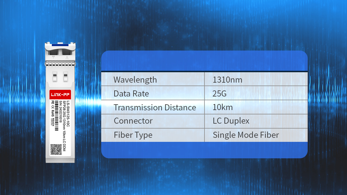
25GBASE LR is a 25Gbps Ethernet optical standard designed for transmission over single-mode fiber up to 10km using a 1310nm wavelength. It is typically implemented in an SFP28 form factor and is widely used for medium-distance data center and campus backbone links.
Definition and Standard Overview
25GBASE LR is defined under IEEE 802.3by and specifies long-reach 25G transmission over single-mode fiber. It uses a distributed feedback (DFB) laser at 1310nm and supports duplex LC connectivity.
The core technical characteristics are summarized below:
| Parameter |
Specification |
| Data Rate |
25.78125Gbps |
| Wavelength |
1310nm |
| Fiber Type |
Single-mode (OS2) |
| Max Distance |
10km |
| Connector |
LC Duplex |
The 25.78125Gbps line rate accommodates encoding overhead defined in the 25G Ethernet standard. Compared to 10GBASE-LR, 25GBASE LR increases bandwidth while maintaining similar reach and fiber type, making it a direct upgrade path in single-mode infrastructures.
How 25GBASE LR Fits into 25G Ethernet Networks
25GBASE LR is primarily used when link distances exceed multimode limits but remain within 10km. It bridges the gap between short-reach intra-rack connections and extended-reach metro optics.
Typical roles in network architecture include:
-
Leaf-to-spine interconnections in medium-to-large data centers
-
Cross-building campus links over existing single-mode fiber
-
Aggregation layer uplinks requiring higher bandwidth than 10G
-
Edge or metro-access segments where distances are beyond 100m–300m
From an infrastructure perspective, 25GBASE LR enables higher port density compared to 40G solutions and lower cost per bit compared to 10G, while avoiding the complexity of CWDM or DWDM systems.
In environments where single-mode fiber is already deployed, 25GBASE LR provides a straightforward bandwidth upgrade without requiring new cabling or optical multiplexing equipment.
📄 Key Specifications of 25GBASE LR Module
When selecting a 25GBASE LR module, the most critical factors are optical performance, electrical characteristics, and fiber infrastructure compatibility. Evaluating these specifications ensures stable 25Gbps transmission over 10km single-mode links without exceeding power or loss budgets.
Optical and Performance Parameters
The optical layer determines whether the 25GBASE LR link can reliably achieve 10km transmission under real deployment conditions.
The key optical specifications are summarized below:
| Parameter |
Typical Value |
| Wavelength |
1310nm |
| Max Distance |
10km |
| Transmitter Type |
DFB Laser |
| Receiver Type |
PIN |
| DOM/DDM Support |
Yes |
Why these parameters matter:
-
1310nm wavelength minimizes dispersion over single-mode fiber at 10km distances.
-
DFB laser provides stable narrow-spectrum output suitable for long-reach links.
-
DOM/DDM (Digital Optical Monitoring) enables real-time visibility into transmit power, receive power, voltage, temperature, and bias current—critical for preventative maintenance.
For procurement evaluation, always verify the optical transmit power range and receiver sensitivity to ensure the link budget aligns with your fiber attenuation and connector loss.
Electrical and Hardware Characteristics
25GBASE LR modules use the SFP28 electrical interface and must meet host-side signal integrity requirements to maintain stable 25Gbps operation.
The essential hardware-level parameters include:
| Parameter |
Typical Range |
| Form Factor |
SFP28 |
| Host Interface |
25G NRZ |
| Power Consumption |
≤1.5W |
| Supply Voltage |
3.3V |
| Hot Pluggable |
Yes |
Evaluation considerations:
-
Power consumption affects switch thermal design and port density.
-
NRZ signaling at 25Gbps requires clean PCB trace design and compliant host hardware.
-
Hot-pluggable support simplifies maintenance and replacement procedures.
Lower power modules are generally preferred in high-density switches to reduce thermal stress and airflow demands.
Fiber Infrastructure Requirements
25GBASE LR is designed specifically for single-mode fiber environments and requires proper link budget planning.
The infrastructure requirements are outlined below:
| Parameter |
Requirement |
| Fiber Type |
OS2 Single-mode |
| Core Size |
9/125µm |
| Connector Type |
LC Duplex |
| Typical Attenuation |
~0.4dB/km |
Deployment guidance:
-
For full 10km reach, total link loss (fiber + connectors + splices) must remain within the module's supported optical budget.
-
Excessive insertion loss from dirty connectors is a common cause of link instability.
-
Polarity and patch panel design should be verified before deployment.
If the existing cabling is multimode (OM3/OM4), 25GBASE LR is not suitable; a 25GBASE SR module should be evaluated instead.
👉 By carefully reviewing optical specifications, electrical characteristics, and fiber compatibility, network planners can confirm whether a 25GBASE LR module will meet performance expectations within their specific 25G Ethernet architecture.
📄 Compatibility and Interoperability Considerations
25GBASE LR transceiver must be compatible with the target switch or router platform to ensure stable link establishment, proper DOM reporting, and long-term reliability. Even when optical specifications match, firmware recognition, EEPROM coding, and interoperability validation determine whether the module will function correctly in production networks.
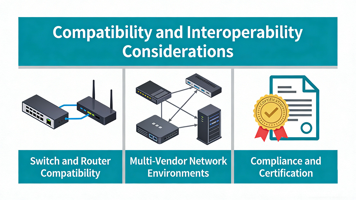
Switch and Router Compatibility
Not all SFP28 ports accept every 25GBASE LR module, even if the hardware interface is standardized. Vendor firmware often checks module identifiers before allowing full functionality.
The main compatibility factors are summarized below:
| Parameter |
Consideration |
| Form Factor |
SFP28 |
| Data Rate Support |
25Gbps |
| EEPROM Coding |
Vendor-specific or multi-vendor |
| DOM Support |
Host-dependent |
Key evaluation points:
-
Some switches require vendor-coded modules to pass firmware validation.
-
Multi-vendor coded modules can be programmed for specific platforms.
-
Firmware upgrades may affect third-party module recognition.
-
DOM visibility depends on both module capability and host support.
Before deployment, confirm that the 25GBASE LR module has been tested against the exact switch model and firmware version in use.
Multi-Vendor Network Environments
In mixed-brand environments, interoperability between different switch vendors is critical for stable 25G links.
To reduce interoperability risks:
-
Verify both ends support 25GBASE LR under IEEE 802.3by.
-
Ensure consistent speed configuration (disable auto-negotiation if required).
-
Confirm matching forward error correction (FEC) settings.
-
Validate optical power levels on both ends after installation.
Link instability in multi-vendor setups is often caused by mismatched FEC modes or unsupported firmware behaviors rather than optical incompatibility.
Compliance and Certification
Standards compliance provides a baseline for interoperability but does not fully replace platform testing.
The most relevant compliance areas include:
| Standard / Certification |
Purpose |
| IEEE 802.3by |
25G Ethernet specification |
| SFP28 MSA |
Mechanical and electrical compatibility |
| RoHS |
Environmental compliance |
| CE / FCC |
Regulatory approval |
Modules compliant with IEEE and SFP28 MSA specifications are designed to meet industry electrical and mechanical standards. However, real-world interoperability still depends on host platform validation.
👉 Ensuring compatibility at both the hardware and firmware levels reduces deployment risk, avoids link negotiation failures, and improves long-term stability in 25G Ethernet networks.
📄 Deployment Scenarios for 25GBASE LR
25GBASE LR is best suited for single-mode fiber links between 2km and 10km where higher bandwidth than 10G is required without moving to more complex optical systems. It is commonly deployed in data centers, enterprise campuses, and metro-access environments that already use OS2 fiber infrastructure.
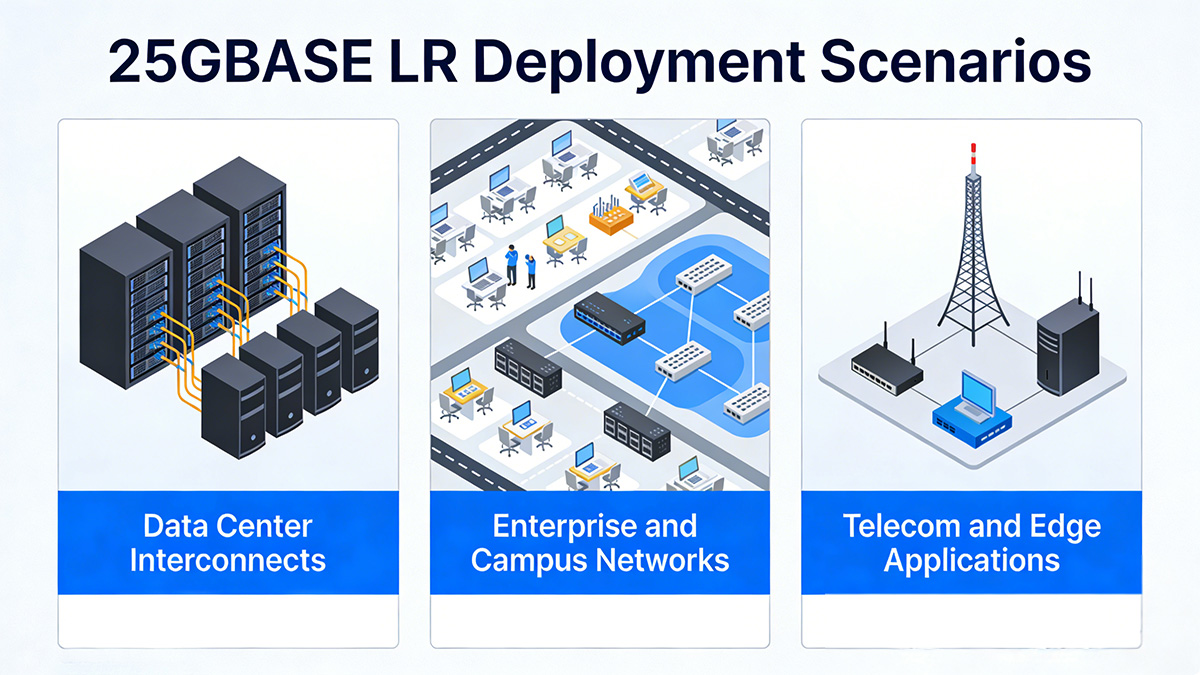
Data Center Interconnects
In data centers, 25GBASE LR is typically used for medium-distance connections that exceed multimode limits but do not require CWDM or DWDM optics.
Common use cases include:
-
Leaf-to-spine uplinks across large data halls
-
Inter-row or inter-building data center links
-
Medium-distance cross-connects over structured single-mode cabling
Why LR is selected in these scenarios:
-
Supports up to 10km without additional amplification
-
Enables higher port density compared to 40G QSFP+ breakout approaches
-
Provides a direct upgrade path from 10GBASE-LR over existing OS2 fiber
In spine-leaf architectures, 25GBASE LR allows consistent single-mode infrastructure across aggregation and distribution layers, simplifying fiber management.
Enterprise and Campus Networks
For enterprise campuses, 25GBASE LR is commonly deployed between buildings or across extended campus environments.
Typical applications:
-
Core-to-aggregation links
-
Building-to-building fiber connections
-
High-bandwidth backbone upgrades from 10G to 25G
When evaluating campus deployment, consider:
-
Existing fiber type (OS2 required)
-
Total link distance (under 10km)
-
Patch panel insertion loss
-
Switch 25G port availability
In many campuses originally wired for 10G single-mode, upgrading to 25GBASE LR requires only module replacement rather than new cabling, preserving prior fiber investments.
Telecom and Edge Applications
In telecom and edge-access networks, 25GBASE LR is used where moderate reach and higher throughput are required without introducing coherent optics.
Common edge scenarios:
-
5G fronthaul or backhaul aggregation
-
Access network aggregation switches
-
Metro edge nodes within 10km radius
The advantages in these environments include:
-
Lower power consumption compared to extended-reach (ER) optics
-
Simpler deployment compared to CWDM/DWDM systems
-
Adequate reach for metro-access rings under 10km
However, if link distances exceed 10km or require optical multiplexing over shared fiber, extended-reach or wavelength-division solutions should be evaluated instead.
📄 25GBASE LR vs Other 25G Optical Modules
25GBASE LR is the preferred option for single-mode links up to 10km, but it is not the only 25G optical interface available. Comparing LR with SR, ER, and wavelength-division variants helps determine whether it matches your distance, fiber type, and infrastructure constraints.
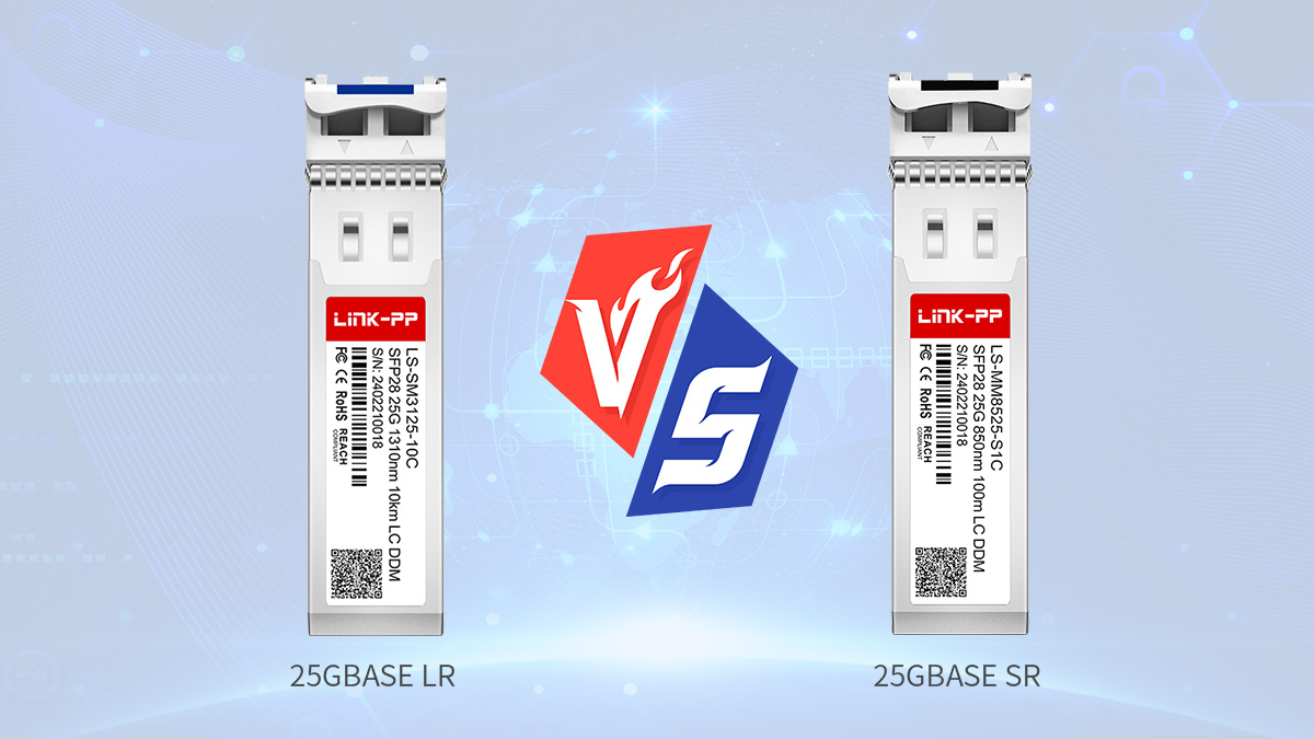
25GBASE SR vs LR
The primary difference between SR and LR lies in fiber type and transmission distance.
For most deployments, the choice can be summarized as follows:
| Parameter |
25GBASE SR |
25GBASE LR |
| Fiber Type |
Multimode (OM3/OM4) |
Single-mode (OS2) |
| Wavelength |
850nm |
1310nm |
| Max Distance |
70–100m |
10km |
| Typical Use |
Intra-rack / short links |
Campus / backbone |
When to choose SR:
-
Link distance is under 100m
-
Multimode fiber is already installed
-
Deployment is limited to the same data hall
When to choose LR:
-
Distance exceeds multimode limits
-
Single-mode fiber infrastructure exists
-
Cross-building or aggregation links are required
If OS2 fiber is available and distance exceeds 100m, 25GBASE LR is generally the more scalable option.
25GBASE ER and CWDM Options
Extended-reach and wavelength-division variants are designed for longer distances or fiber optimization scenarios.
Their positioning can be summarized below:
| Parameter |
25GBASE LR |
25GBASE ER |
| Max Distance |
10km |
20–40km (typical) |
| Laser Type |
DFB |
Higher power DFB / cooled |
| Power Consumption |
Lower |
Higher |
| Deployment Complexity |
Standard SMF |
May require stricter link budget planning |
ER modules are appropriate when:
CWDM-based 25G optics are used when:
-
Multiple wavelengths must share the same fiber
-
Fiber resources are limited
-
Network design includes passive multiplexers
However, ER and CWDM solutions typically introduce higher cost, higher power consumption, and stricter planning requirements compared to standard LR.
When 25GBASE LR Is the Best Fit
25GBASE LR is the optimal choice under the following conditions:
-
Link distance between 2km and 10km
-
Existing OS2 single-mode fiber infrastructure
-
No need for wavelength multiplexing
-
Standard 25G SFP28 port availability
-
Balanced requirement between reach and power efficiency
It offers a middle ground: significantly longer reach than SR while avoiding the added complexity and power demands of ER or WDM-based modules.
👉 In most enterprise, campus, and medium-scale data center backbones, 25GBASE LR provides sufficient reach, predictable performance, and straightforward deployment without introducing unnecessary optical system overhead.
📄 Selection Criteria for 25GBASE LR Modules
Selecting a 25GBASE LR module requires evaluating more than distance and wavelength. Long-term reliability, manufacturing quality, compatibility validation, and lifecycle cost all influence network stability and operational efficiency.
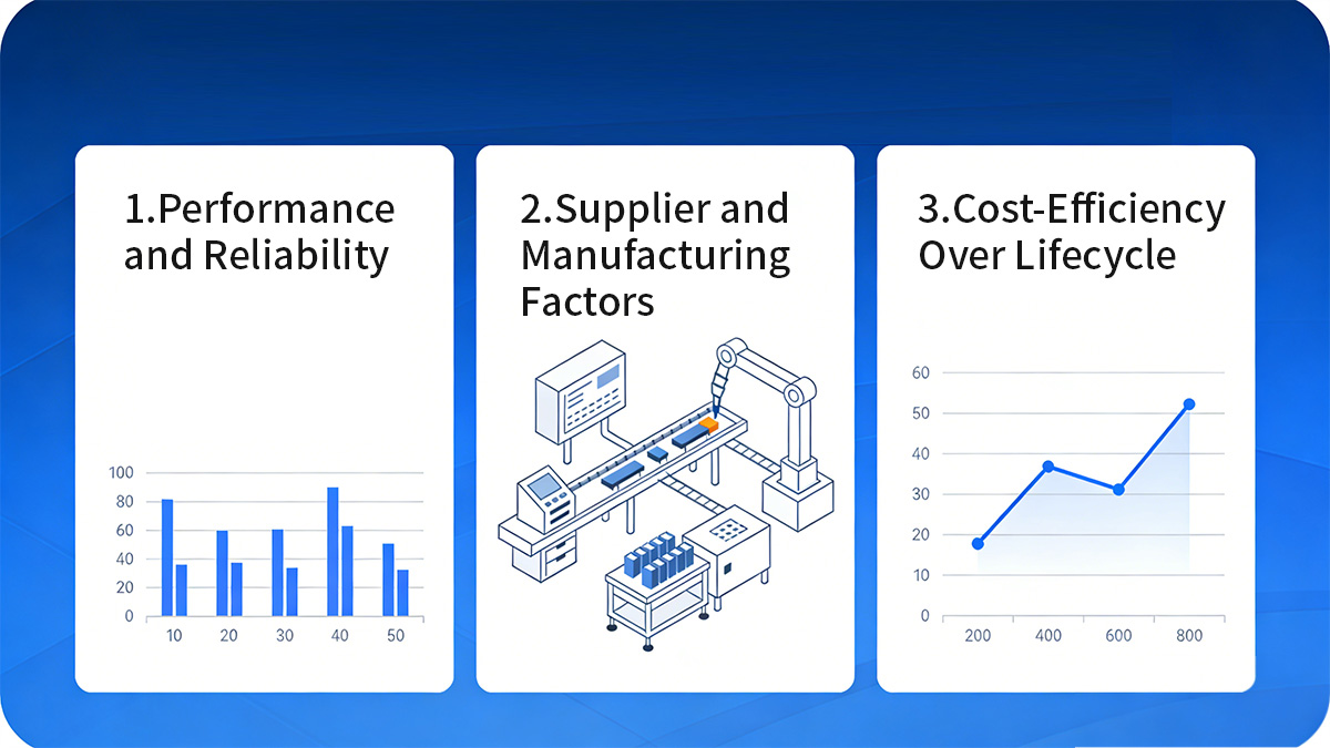
Performance and Reliability
A qualified 25GBASE LR module must maintain stable 25Gbps transmission over 10km under real operating conditions, including temperature fluctuations and continuous workload.
The most relevant reliability indicators include:
| Parameter |
Evaluation Focus |
| Optical Budget |
TX power & RX sensitivity margin |
| Power Consumption |
≤1.5W typical |
| Operating Temperature |
0–70°C (commercial) or extended range |
| MTBF |
Manufacturer specification |
| DOM Accuracy |
Real-time monitoring precision |
What to verify:
-
Ensure sufficient optical margin beyond calculated fiber attenuation.
-
Confirm stable operation within the switch's airflow and thermal profile.
-
Review MTBF data to estimate long-term failure probability.
-
Validate DOM readings for accurate diagnostics and preventive maintenance.
Modules with consistent optical output and low power drift over temperature variations are more suitable for high-density switch environments.
Supplier and Manufacturing Factors
Manufacturing quality directly affects module consistency, coding accuracy, and interoperability stability.
When evaluating suppliers, consider:
-
Component sourcing – Quality of DFB lasers and receiver components.
-
Production testing – 100% optical testing, BER verification, and burn-in procedures.
-
Compatibility validation – Testing against major switch platforms and firmware versions.
-
Traceability – Serial number tracking and production batch records.
A module that meets IEEE specifications but lacks proper platform validation may still cause intermittent link issues. Verified compatibility testing reduces deployment uncertainty.
Cost-Efficiency Over Lifecycle
Initial unit cost is only one part of the overall network investment. Lifecycle cost includes replacement rates, maintenance effort, and operational risk.
Cost-efficiency evaluation should include:
| Factor |
Impact on Lifecycle |
| Failure Rate |
Replacement frequency |
| Power Efficiency |
Switch thermal load |
| Compatibility Stability |
Reduced troubleshooting time |
| Warranty Period |
Risk mitigation |
Lower failure rates and stable interoperability reduce operational interruptions. In large-scale deployments, even small differences in reliability can significantly affect maintenance overhead.
📄 Installation and Deployment Best Practices
Proper installation directly affects the stability and lifespan of a 25GBASE LR link. Even when specifications and compatibility are correct, poor fiber handling, incorrect testing, or inadequate environmental planning can reduce optical margin and cause intermittent issues.
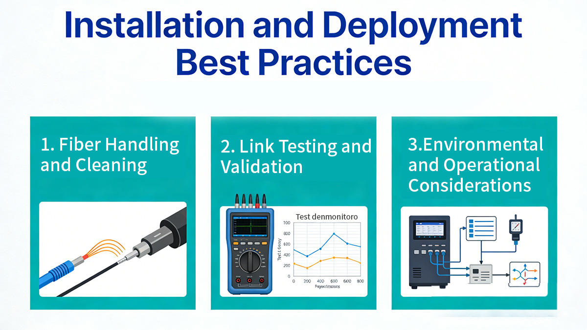
Fiber Handling and Cleaning
Most 25GBASE LR link failures are caused by contamination or excessive insertion loss rather than module defects.
Before commissioning a link, follow these essential steps:
-
Inspect all LC connectors using a fiber inspection scope.
-
Clean connectors with approved fiber cleaning tools before insertion.
-
Verify polarity (Tx to Rx alignment).
-
Avoid excessive bending below minimum bend radius.
The typical loss contributors are:
| Loss Source |
Typical Impact |
| Fiber attenuation |
~0.4dB/km |
| LC connector pair |
0.2–0.5dB |
| Splice point |
0.1–0.3dB |
| Contamination |
Variable / unpredictable |
Even small contamination can introduce unpredictable reflection and attenuation, reducing link margin below receiver sensitivity thresholds.
Maintaining clean connectors preserves the designed optical budget and ensures stable 10km transmission.
Link Testing and Validation
After physical installation, validation ensures that the 25GBASE LR link operates within acceptable optical limits.
Recommended validation process:
-
Measure transmit and receive optical power using DOM readings.
-
Compare measured RX power against module receiver sensitivity.
-
Confirm correct speed configuration (25Gbps).
-
Verify FEC settings on both ends.
-
Run traffic or BER testing if required.
A stable 25GBASE LR link should show consistent RX power without large fluctuations. Sudden drops typically indicate connector contamination or excessive loss.
For new fiber deployments, OTDR testing can identify unexpected splice or attenuation issues before activating production traffic.
Environmental and Operational Considerations
25GBASE LR modules operate reliably within defined thermal and electrical limits. High-density switch environments require careful planning.
Key operational considerations:
-
Ensure adequate airflow direction alignment with switch design.
-
Avoid exceeding specified operating temperature range (0–70°C typical commercial).
-
Monitor module temperature through DOM readings.
-
Consider total power budget per switch chassis when deploying multiple 25G ports.
Lower power consumption modules reduce cumulative thermal stress in top-of-rack and spine switches.
👉 By combining clean fiber practices, structured validation, and proper environmental control, 25GBASE LR deployments can achieve predictable 25Gbps performance with sufficient optical margin for long-term stability.
📄 Common Issues and Troubleshooting
Most 25GBASE LR link problems are caused by compatibility mismatches, fiber loss issues, or configuration inconsistencies rather than hardware failure. Systematically verifying optical power levels, host settings, and physical connectivity typically resolves the majority of 25Gbps link issues.
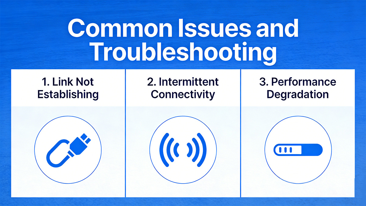
Link Not Establishing
If a 25GBASE LR link does not come up, the root cause is usually configuration or compatibility related.
The most common causes include:
-
Switch port not configured for 25Gbps
-
Unsupported or incorrect EEPROM coding
-
FEC mismatch between link endpoints
-
Tx/Rx polarity reversed
-
Optical loss exceeding link budget
A structured diagnostic approach:
-
Confirm port speed is manually set to 25Gbps (if auto-negotiation is disabled).
-
Verify module recognition in the switch interface.
-
Check DOM readings for transmit and receive optical power.
-
Swap fiber polarity if no RX signal is detected.
-
Compare measured RX power with receiver sensitivity threshold.
If RX power is below sensitivity level, the issue is typically excessive insertion loss or fiber attenuation.
Intermittent Connectivity
Intermittent link flapping is often related to unstable optical margin or firmware behavior rather than total link failure.
Typical root causes:
-
Dirty LC connectors
-
Marginal optical power close to receiver sensitivity
-
Firmware compatibility inconsistencies
-
Temperature-induced power drift
The optical margin concept is critical here:
| Condition |
Expected Behavior |
| RX power well above sensitivity |
Stable link |
| RX power near threshold |
Occasional flapping |
| RX power below threshold |
Link down |
If the receive power is too close to the sensitivity limit, even small environmental variations can cause link instability.
Cleaning connectors and ensuring at least 2–3dB optical margin above sensitivity significantly improves stability.
Performance Degradation
When a 25GBASE LR link establishes successfully but shows packet errors or throughput reduction, deeper analysis is required.
Common contributing factors:
-
Incorrect FEC configuration
-
Aging or high-attenuation fiber
-
Excessive connector reflections
-
Overheating due to poor airflow
Troubleshooting steps:
-
Verify FEC mode matches on both sides.
-
Check CRC or interface error counters.
-
Monitor module temperature via DOM.
-
Perform OTDR testing if fiber degradation is suspected.
Persistent performance degradation often indicates marginal optical budget rather than immediate hardware failure.
👉 A methodical approach—checking compatibility, validating optical power levels, confirming configuration alignment, and ensuring clean fiber connections—resolves the majority of 25GBASE LR deployment issues while minimizing unnecessary module replacement.
📄 FAQ About 25GBASE LR
Q1: Can 25GBASE LR operate over distances shorter than 1km?
Yes. Although it is designed for up to 10km, 25GBASE LR can operate over short single-mode links as long as the received optical power does not exceed the maximum input threshold. In very short runs (e.g., under 500m), an optical attenuator may be required to prevent receiver overload.
Q2: Is 25GBASE LR backward compatible with 10GBASE-LR?
No. 25GBASE LR operates at 25Gbps and is not speed-compatible with 10Gbps ports. Even though both use 1310nm single-mode optics and LC connectors, the electrical signaling and line rates are different.
Q3: Does 25GBASE LR require auto-negotiation to be enabled?
Not necessarily. Many 25G deployments disable auto-negotiation and manually configure port speed and FEC. Whether auto-negotiation is required depends on the switch platform and network design policy.
Q4: Can 25GBASE LR be used in breakout configurations?
No. 25GBASE LR is a single-lane SFP28 optical module and does not support breakout into multiple lower-speed interfaces. Breakout scenarios typically involve QSFP-based modules rather than SFP28.
Q5: Is forward error correction (FEC) mandatory for 25GBASE LR?
It depends on the host platform. Some switches require RS-FEC for 25G operation, while others allow configurable FEC modes. Both link endpoints must use matching FEC settings to establish a stable connection.
Q6: Can 25GBASE LR operate over older single-mode fiber installations?
Yes, in most cases. Standard OS2 fiber supports 1310nm transmission effectively. However, legacy fiber with high attenuation, excessive splices, or poor connector quality may reduce available link margin and require testing before deployment.
📄 Conclusion
25GBASE LR is the practical choice for 25Gbps single-mode connections up to 10km, offering a balanced combination of reach, power efficiency, and deployment simplicity for data center, campus, and metro-access networks. When optical budget, compatibility validation, and fiber infrastructure are properly evaluated, 25GBASE LR enables stable and scalable 25G Ethernet expansion without introducing unnecessary system complexity.
For organizations planning to standardize or expand their 25G single-mode deployments, selecting thoroughly tested and compatibility-verified 25GBASE LR modules is essential to ensure long-term network reliability. Explore validated 25GBASE LR SFP28 solutions at the LINK-PP Official Store to support your next 25G network upgrade with confidence.