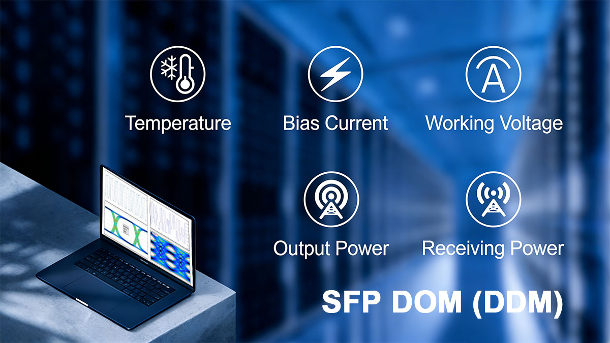
SFP DOM (Digital Optical Monitoring), also referred to as DDM, is a standardized mechanism that allows optical transceivers to report real-time operating parameters such as optical power, temperature, voltage, and laser bias current. Defined primarily by SFF-8472, SFP DOM transforms optical modules from passive components into measurable, monitorable network elements.
In modern fiber networks—where 10G, 25G, and higher-speed links are deployed across data centers, enterprise backbones, and metro access layers—link reliability is no longer validated solely by link LEDs or error counters. Operators increasingly rely on DOM telemetry to verify link health, detect degradation trends, and diagnose faults before service impact occurs.
However, DOM data is often misunderstood or misused. Reported values vary by vendor, calibration method, and implementation, and DOM readings are not equivalent to laboratory-grade optical measurements. Misinterpreting DOM accuracy, thresholds, or EEPROM encoding can lead to incorrect conclusions during commissioning or troubleshooting.
This article provides a standards-based, engineering-level explanation of SFP DOM, covering how it works, which parameters matter, how accurate the readings really are, and how DOM should be used—and not used—in real-world optical networks. The goal is to help network engineers, system integrators, and procurement teams interpret DOM data correctly and apply it with confidence.
By the end of this guide, you will understand:
-
What SFP Modules DOM measures and why it exists
-
How DOM data is accessed and encoded
-
The practical accuracy limits of DOM readings
-
Best practices for monitoring, validation, and deployment decisions
This foundation is essential for anyone designing, operating, or sourcing optical transceivers in production networks.
✅ What Is SFP DOM (DDM)? Definition, Purpose, and Standards
SFP DOM (Digital Optical Monitoring), also known as DDM, is a standardized capability that allows an SFP or SFP+ optical transceiver to report internal operating parameters—such as optical power, temperature, voltage, and laser bias current—via a digital interface. DOM enables real-time visibility into transceiver health and link conditions without external test equipment.
DOM was introduced to address a fundamental limitation of traditional optical links: link status alone is not a health indicator. A green link LED confirms signal presence, but it provides no insight into margin, degradation, or environmental stress. By contrast, DOM exposes quantitative telemetry that allows operators to:
-
Verify optical power levels during link commissioning
-
Detect gradual signal degradation before errors occur
-
Correlate temperature or voltage anomalies with failures
-
Support proactive maintenance and capacity planning
It is important to note that DOM is optional within the SFP ecosystem. While most modern SFP, SFP+, and higher-speed modules support DOM, compliance depends on vendor implementation and proper EEPROM programming. Additionally, DOM reporting does not guarantee measurement accuracy; accuracy requirements and calibration methods are explicitly defined—and limited—by SFF-8472.
Why DOM Exists: Quantitative Monitoring vs. Link / LOS LEDs
Traditional Link or LOS (Loss of Signal) LEDs provide only binary status—signal present or absent. They do not indicate signal quality, margin, degradation trends, or environmental stress. A link can remain “up” while operating close to receiver sensitivity or thermal limits.
SFP DOM addresses this limitation by exposing quantitative, continuous telemetry, allowing engineers to assess how healthy a link is, not just whether it is active.
| Indicator |
What It Shows |
Limitations |
| Link / LOS LED |
Signal presence |
No margin, no trend, no diagnostics |
| SFP DOM |
Power, temperature, voltage, bias current |
Monitoring only, not lab-grade |
DOM therefore complements—but does not replace—traditional link indicators.
The Role of SFF-8472 in SFP DOM
SFF-8472 is the authoritative specification that defines:
-
Which diagnostic parameters must be supported
-
How values are encoded and scaled
-
The I²C memory map used for DOM data (A2h)
-
Alarm and warning thresholds
SFF-8472 does not define optical reach, performance limits, or guaranteed accuracy—that responsibility remains with IEEE standards (such as 10GBASE-LR) and vendor datasheets. Instead, SFF-8472 ensures that DOM data is consistently formatted and accessible across vendors.
In practice, SFP DOM serves as a monitoring and diagnostic aid, not a replacement for calibrated optical test instruments. Understanding the standard behind DOM is the first step toward interpreting its data correctly and using it effectively in operational networks.
✅ How SFP DOM Works: I²C Interface, A0h vs A2h Memory Maps, and Data Encoding
SFP DOM operates over a two-wire I²C serial interface, shared between the host system and the optical module. This interface allows in-band access to both static identification data and real-time diagnostic measurements without interrupting traffic on the optical link.
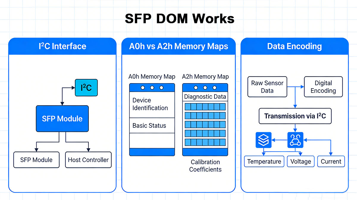
A0h vs A2h: Two Logical Address Spaces
SFF-8472 defines two primary I²C address spaces, each serving a distinct purpose:
-
A0h (Serial ID memory)
Contains static, read-only information that identifies the transceiver, including vendor name, part number, wavelength, supported standards, and nominal link reach. This data is programmed at manufacturing time and does not change during operation.
-
A2h (Diagnostic monitoring memory)
Contains dynamic, real-time operating data reported by the module’s internal sensors. This is where DOM parameters—such as optical power, temperature, voltage, and laser bias current—are stored and periodically updated.
Separating identification data (A0h) from diagnostic data (A2h) allows host systems to inventory modules and monitor their health independently, using the same standardized access method.
Data Encoding and Units
DOM values in the A2h address space are encoded in fixed-width digital formats defined by SFF-8472. Most parameters use 16-bit registers, with scaling factors that convert raw values into engineering units:
-
Optical power is typically encoded in linear units and converted to dBm by the host.
-
Temperature is reported with a signed format and fractional resolution, allowing sub-degree precision.
-
Voltage and bias current are reported in scaled integer form, requiring host-side conversion.
Because DOM data is digitally encoded and periodically refreshed, the values should be interpreted as sampled telemetry, not instantaneous analog measurements.
Update Behavior and Polling
DOM readings are updated internally by the SFP module at defined intervals. Host systems typically poll A2h registers through:
Polling frequency should be balanced to avoid unnecessary I²C traffic while still capturing meaningful trends over time.
Understanding the separation between A0h and A2h memory, as well as how DOM data is encoded and retrieved, is essential for correctly interpreting readings—especially when comparing modules from different vendors or validating measurements against external test equipment.
✅ Key SFP DOM Parameters and What They Mean
SFP DOM exposes a defined set of diagnostic parameters that reflect both optical signal conditions and internal module health. Interpreting these values correctly is essential for commissioning, monitoring, and troubleshooting fiber links. Each parameter has a specific unit, typical operating range, and practical meaning in live networks.
Core SFP DOM Parameters
| DOM Parameter |
Unit |
What It Represents |
Primary Engineering Use |
| Tx Optical Power |
dBm |
Optical launch power into fiber |
Margin verification, laser aging |
| Rx Optical Power |
dBm |
Optical power received |
Link loss, cleanliness, faults |
| Laser Bias Current |
mA |
Drive current for the laser |
Laser health, end-of-life trend |
| Module Temperature |
°C |
Internal transceiver temperature |
Thermal stress, derating risk |
| Supply Voltage |
V |
Module operating voltage |
Host stability, power integrity |
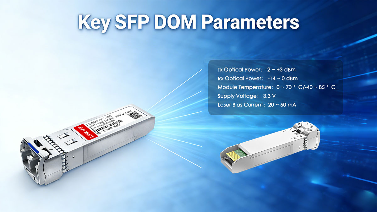
1. Tx Optical Power (dBm)
Transmit (Tx) optical power represents the average optical output launched into the fiber by the module’s laser, expressed in dBm.
-
Typical range (10G-class optics): −8 to +1 dBm (varies by standard and module type)
-
Reported via DOM as a measured output, not a guaranteed spec limit
Operational insight:
Tx power should remain relatively stable over time. A gradual decline may indicate laser aging or temperature stress, while an unexpected increase could point to calibration drift or vendor-specific encoding differences. Tx power alone does not confirm link health—it must be evaluated together with Rx power and link budget.
2. Rx Optical Power (dBm)
Receive (Rx) optical power measures the optical signal level arriving at the receiver photodiode.
-
Typical operating window: between receiver sensitivity and overload threshold
-
Strongly influenced by fiber loss, connectors, splices, and cleanliness
Operational insight:
Rx power is the most commonly used DOM parameter during deployment. Values near sensitivity margins increase the risk of errors, while values near overload can stress the receiver. Sudden drops in Rx power often indicate connector contamination, fiber damage, or patching errors.
3. Laser Bias Current (mA)
Laser bias current is the electrical current used to drive the laser to maintain its target output power.
Operational insight:
Bias current typically increases slowly over the lifetime of a module as the laser ages. A rising bias current with stable Tx power is a normal aging pattern, whereas sharp changes may indicate impending laser failure or temperature-related stress.
4. Module Temperature (°C)
Module temperature is measured internally near the optical and electrical components.
Operational insight:
Temperature directly affects laser performance, wavelength stability, and long-term reliability. Persistent operation near the upper limit accelerates aging and may reduce optical margin. Temperature trends are more meaningful than single-point readings.
5. Supply Voltage (V)
Supply voltage reflects the module’s internal operating voltage, usually derived from a 3.3 V rail.
Operational insight:
Voltage anomalies may point to host-side power issues, backplane instability, or slot-level faults. Voltage readings are primarily useful for platform diagnostics, not optical troubleshooting.
Interpreting Parameters Together
No single DOM value should be evaluated in isolation. Effective use of DOM relies on correlating multiple parameters over time, rather than reacting to absolute numbers alone. Baseline measurements taken at installation provide the most reliable reference for detecting abnormal behavior later in the module’s lifecycle.
Understanding what each DOM parameter represents—and its limitations—sets the stage for assessing measurement accuracy, calibration, and real-world reliability, which are addressed in the next section.
✅ Accuracy, Calibration, and Limits of DOM Readings
SFP DOM provides valuable operational visibility, but it is not a precision measurement system. Understanding the accuracy limits and calibration model defined by the standard is essential to avoid misinterpretation—especially when DOM data is compared across vendors or used for acceptance testing.
Typical Accuracy Ranges
DOM accuracy is bounded by SFF-8472, not by IEEE optical performance standards. Typical ranges seen in compliant modules are:
-
Optical power (Tx / Rx): approximately ±3 dB
-
Laser bias current: typically ±10%
-
Module temperature: around ±3 °C
-
Supply voltage: typically ±3%
These tolerances are sufficient for monitoring and trend analysis, but they are orders of magnitude less precise than calibrated optical test instruments. Absolute values should therefore be treated as indicative, not definitive.
Internal vs. External Calibration (SFF-8472)
SFF-8472 allows two calibration approaches:
-
Internal calibration
Sensor offsets and scaling are applied inside the module. The host reads already-adjusted values. This is the most common implementation.
-
External calibration
Raw sensor values are reported, and calibration coefficients stored in EEPROM are applied by the host system.
Both methods are standards-compliant, but implementation quality varies by vendor. Differences in calibration approach can result in noticeable offsets when comparing DOM readings between modules from different manufacturers.
Temperature and Voltage Dependency
DOM sensors operate within the same thermal and electrical environment as the transceiver itself. As a result:
-
Optical power readings shift with temperature
-
Bias current rises at higher operating temperatures
-
Voltage variation can influence sensor resolution and stability
These dependencies mean that short-term fluctuations are normal and should not automatically be treated as faults. Trend direction and persistence matter more than instantaneous values.
Why DOM Is for Trends and Alarms—not Certification
DOM was designed to support monitoring, diagnostics, and predictive maintenance, not formal link certification.
DOM cannot replace:
-
A calibrated optical power meter
-
An OTDR for fiber characterization
-
Acceptance testing required for SLA or compliance audits
Its strength lies in relative change detection: identifying degradation, abnormal behavior, or environmental stress before service impact occurs. Used correctly, DOM is an early-warning system—not a final authority.
Understanding these limits ensures DOM data is applied appropriately, setting the stage for effective operational use in commissioning, monitoring, and troubleshooting workflows.
✅ Using SFP DOM in Real Networks: Monitoring, Troubleshooting, and Maintenance
When used correctly, DOM becomes a practical engineering tool, not just a diagnostic feature on a SFP datasheet. Its real value emerges in day-to-day operations—during commissioning, ongoing monitoring, and long-term maintenance—where visibility into trends matters more than absolute measurements.
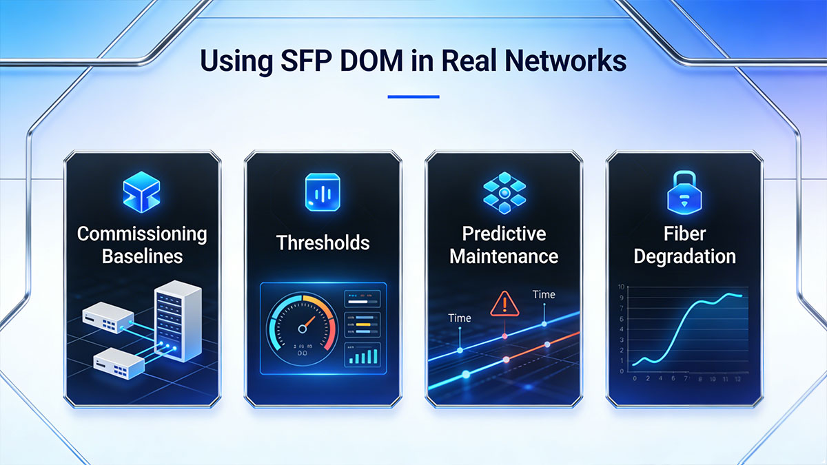
Commissioning Baselines
During initial deployment, DOM readings should be captured immediately after link activation and recorded as baseline values.
Typical baseline parameters include:
These baselines serve as a reference for future comparisons. Without them, it becomes difficult to determine whether a later reading reflects normal variation or early degradation.
Thresholds and Alarms
Most network platforms allow DOM-based warning and alarm thresholds to be configured using values defined in SFF-8472 or vendor recommendations.
Effective thresholding focuses on:
-
Rx power approaching sensitivity limits
-
Rapid changes in bias current
-
Sustained high module temperature
Alarms should be set to detect abnormal trends, not to trigger on minor, expected fluctuations. Poorly tuned thresholds often generate noise rather than actionable insight.
Trend Analysis and Predictive Maintenance
DOM is most powerful when data is collected over time and analyzed as a trend.
Examples of actionable trends include:
-
Slowly decreasing Rx power indicating connector contamination or fiber aging
-
Increasing laser bias current signaling laser wear
-
Rising operating temperature due to airflow or density changes
These trends enable predictive maintenance, allowing issues to be addressed during planned windows instead of after link failure.
Early Detection of Fiber Degradation and Laser Aging
Many fiber and transceiver failures develop gradually. DOM provides early indicators that are invisible to link LEDs or error counters.
-
Fiber microbends, dirty connectors, or stressed patch cords often appear first as Rx power drift
-
Laser aging typically manifests as increasing bias current before output power drops
By correlating DOM parameters, operators can identify and resolve issues before service quality is affected, improving uptime and extending component life.
Used in this way, DOM/DDM supports a proactive operational model—one that aligns with modern network reliability and lifecycle management practices.
✅ Validating DOM Data: Power Meter, OTDR, or DOM?
SFP DOM provides continuous visibility, but validation requires the right tool for the right task. Understanding how DOM compares with external instruments—and when to use each—is essential for sound engineering decisions and accurate fault isolation.
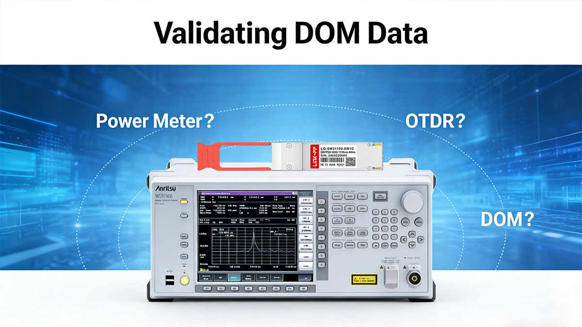
DOM vs Optical Power Meter: Relative vs Absolute Measurement
SFP monitoring and optical power meters serve different purposes:
-
SFP DOM
Provides relative, in-service monitoring. It is ideal for observing trends, detecting changes, and triggering alarms while traffic is live.
-
Optical Power Meter
Provides absolute, calibrated measurements. It is required for acceptance testing, SLA validation, and precise link budget verification.
Because DOM accuracy is typically limited to ±3 dB, it should not be used to certify link performance. However, DOM is extremely effective at identifying directional changes—for example, whether received power is dropping over time.
When an OTDR Is Required
An Optical Time-Domain Reflectometer (OTDR) is necessary when the problem lies within the fiber plant itself.
Use an OTDR when:
-
Rx power suddenly drops without a clear cause
-
Fiber damage, excessive bends, or bad splices are suspected
-
The physical location of loss or reflection must be identified
DOM can indicate that a problem exists, but only an OTDR can determine where it is along the fiber path.
Step-by-Step DOM Validation Workflow
A structured validation approach reduces guesswork and avoids misdiagnosis:
-
Record DOM baselines at commissioning (Tx power, Rx power, temperature, bias current).
-
Compare current DOM readings against historical values, not just nominal specs.
-
Confirm Rx power with a calibrated power meter if values approach sensitivity or overload thresholds.
-
Use an OTDR if power loss is confirmed but the cause is unclear.
-
Recheck DOM after remediation to ensure parameters return to baseline ranges.
This workflow leverages DOM for continuous monitoring while reserving external tools for precision measurement and root-cause analysis.
In practice, DOM, power meters, and OTDRs are complementary. Using them together provides both operational efficiency and engineering accuracy—without over-relying on any single data source.
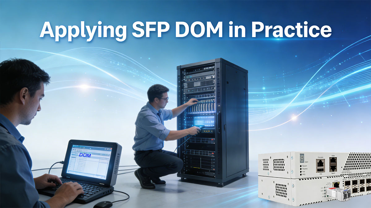
✅ Applying SFP DOM in Practice: Best Practices, Pitfalls, and Sourcing
Effective use of SFP DOM depends as much on process and discipline as on the technology itself. The following best practices, common pitfalls, and procurement considerations summarize how to apply DOM correctly across design, operations, and sourcing.
Best Practices: Baselines, Polling, and Thresholds
-
Establish baselines at commissioning
Capture Tx power, Rx power, bias current, temperature, and voltage immediately after deployment. Baselines are the only reliable reference for long-term comparison.
-
Use sensible polling intervals
DOM data changes slowly. Polling every few minutes—or even longer for trend analysis—is sufficient and avoids unnecessary I²C load.
-
Set thresholds for trends, not noise
Alarms should focus on sustained deviation or rate of change, not minor fluctuations. Poorly tuned thresholds generate alerts without operational value.
Common Pitfalls: Where DOM Is Often Misused
-
Cross-vendor comparison errors
DOM values from different vendors are not guaranteed to align due to calibration differences. Comparing absolute numbers across brands often leads to false conclusions.
-
Disabled or partially implemented DOM
Some low-cost or legacy modules advertise DOM support but do not fully implement SFF-8472 or report static values.
-
Misinterpreted units and scaling
DOM data is digitally encoded. Incorrect unit conversion or misreading raw values can result in significant interpretation errors.
RFQ Checklist: What to Request for Reliable DOM
When sourcing optical transceiver, DOM capability should be explicitly addressed in RFQs and qualification documents:
-
Explicit SFF-8472 compliance (including A2h diagnostics)
-
Calibration method disclosure (internal vs. external)
-
Defined accuracy ranges for optical power and temperature
-
DOM functionality covered under warranty and RMA terms
Including these requirements reduces interoperability risk and ensures DOM data can be trusted in operational environments.
Applied correctly, SFP DOM becomes a powerful operational signal. Applied casually, it becomes misleading noise. Clear practices and informed procurement are the difference.
✅ SFP DOM FAQs
Q1: Can SFP DOM replace a power meter?
No. SFP DOM cannot replace a calibrated optical power meter. DOM provides in-service, relative monitoring with limited accuracy, while a power meter delivers absolute, traceable measurements required for link certification, acceptance testing, and SLA validation.
Q2: What is typical SFP DOM accuracy?
Typical accuracy is approximately ±3 dB for optical power, ±3 °C for temperature, and ±3% for supply voltage, depending on vendor implementation and calibration method. These ranges are sufficient for trend monitoring and alarms, but not for precision measurement.
Q3: Which I²C address stores DOM data?
SFP DOM data is stored at the A2h I²C address, as defined by SFF-8472. Static module identification data (vendor, wavelength, reach) resides at A0h, while real-time diagnostic values are accessed via A2h.
Q4: Why does Rx power differ between vendors?
Rx power readings can differ due to calibration offsets, sensor design, encoding methods, and temperature compensation differences. SFF-8472 standardizes access and format, but it does not guarantee identical absolute readings across vendors.
✅ SFP DOM Summary
SFP DOM is a powerful operational tool when its purpose and limits are clearly understood.
-
DOM delivers visibility, not certification. It provides continuous insight into transceiver health and link conditions, but it does not replace calibrated test instruments for acceptance or compliance.
-
Its real value lies in trends, alarms, and prevention. By tracking changes in optical power, temperature, and bias current over time, DOM enables early fault detection and proactive maintenance.
-
Correct interpretation depends on standards awareness. Knowing how SFF-8472 defines DOM—and what it does not define—is essential for reliable use in production networks.
When applied with proper baselines, thresholds, and validation workflows, SFP DOM supports higher uptime, lower troubleshooting cost, and longer component lifecycles.
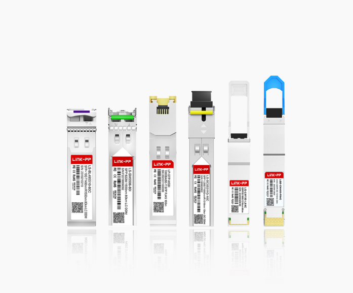
Engineering Validation & Qualified DOM Modules
For deployments that require verified SFF-8472 compliance, consistent DOM calibration, and engineering-level support, explore LINK-PP SFP Modules. LINK-PP provides qualified optical modules, compatibility validation, and technical assistance to help ensure DOM data is reliable from lab testing through long-term operation.
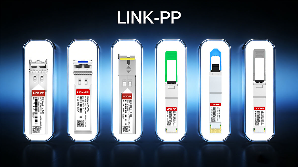
👉 Request samples, validation support, or specification details from LINK-PP Official Store to integrate DOM-enabled transceivers with confidence.