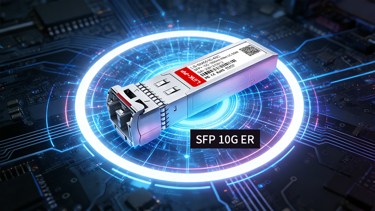
SFP 10G ER is a 10Gbps extended-reach optical transceiver designed to support transmission distances up to 40km over single-mode fiber using a 1550nm wavelength. As a standardized implementation of 10GBASE-ER defined by IEEE 802.3ae, it is widely deployed in metro networks, campus backbones, and medium-range data center interconnect scenarios where 10G long-distance connectivity is required without moving to DWDM systems.
Compared with shorter-reach optics such as LR, SFP 10G ER provides a significantly higher optical power budget, enabling stable performance over longer fiber spans while maintaining the compact SFP+ form factor. For network engineers and technical buyers evaluating 10G optical modules, understanding its specifications, link budget characteristics, compatibility considerations, and deployment requirements is essential to ensure reliable 40km transmission and standards compliance.
This technical guide explains how SFP 10G ER works, outlines its core specifications, compares it with other 10G optical modules, and provides structured guidance for selection and deployment in real-world networks.
⏩ What Is an SFP 10G ER Transceiver?
An SFP 10G ER transceiver is a 10Gbps extended-reach optical module designed to transmit data up to 40km over single-mode fiber at 1550nm, compliant with 10GBASE-ER specifications defined by IEEE 802.3ae. It uses the SFP+ form factor, supports hot-pluggable operation, and is primarily deployed in metro and long campus backbone environments where 10G long-distance connectivity is required.
Unlike shorter-reach 10G optics, the ER variant provides a higher optical power budget to compensate for fiber attenuation over longer distances while maintaining interoperability within standardized 10G Ethernet environments.
Definition and Role in 10G Networks
SFP 10G ER serves as a long-distance physical layer interface for 10Gbps Ethernet networks, extending connectivity to 40km without requiring wavelength multiplexing systems.
Its role in a 10G network typically includes:
-
Extending Layer 2 or Layer 3 links between buildings or sites
-
Supporting metro aggregation connections
-
Enabling backbone uplinks over single-mode fiber
-
Providing standardized 10GBASE-ER optical connectivity
From a protocol perspective, it operates at 10Gbps line rate and integrates directly with SFP+ ports on switches, routers, and network interface cards. Because it adheres to IEEE 10GBASE-ER specifications, it ensures interoperability across compliant network platforms.
Where SFP 10G ER Fits in Optical Standards
SFP 10G ER is part of the 10GBASE family of Ethernet physical layer standards. Within this family, it represents the extended-reach option optimized for long single-mode fiber spans.
It is best understood in relation to other common 10G optical standards:
The ER standard operates at 1550nm because this wavelength offers lower attenuation in single-mode fiber, enabling longer transmission distances. Compared to LR, ER requires stronger transmit optical power and higher receiver sensitivity to maintain signal integrity across extended spans.
In standardized Ethernet architectures, SFP 10G ER occupies the segment between medium-range optics (LR) and more specialized long-haul or DWDM solutions, making it suitable for 10G links that exceed 10km but do not require complex optical transport systems.
⏩ Key Specifications of SFP 10G ER Modules
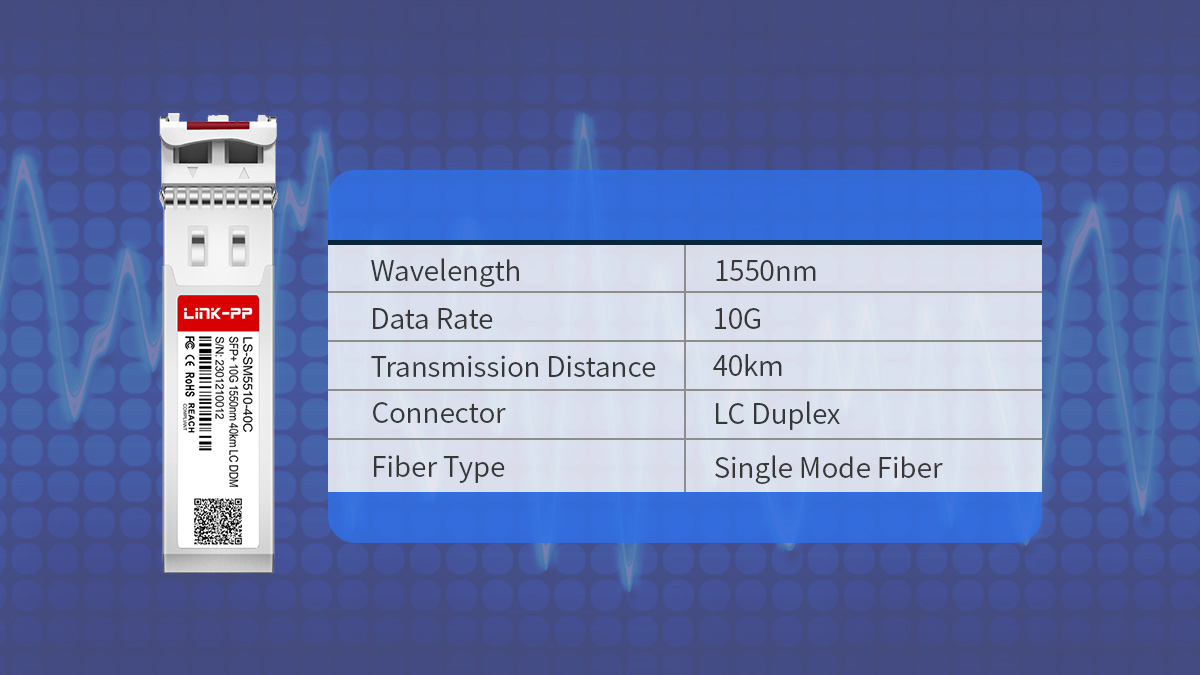
SFP 10G ER modules are defined by their 10Gbps data rate, 1550nm operating wavelength, and up to 40km transmission distance over OS2 single-mode fiber. They comply with 10GBASE-ER requirements and are engineered to provide sufficient optical power budget for long-distance Ethernet links without external amplification.
Understanding the core optical, electrical, and mechanical specifications is essential for correct link planning and equipment compatibility.
Optical and Electrical Parameters
SFP 10G ER operates at 1550nm and is optimized for long-distance single-mode fiber transmission with a typical maximum reach of 40km.
| Parameter |
Typical Value |
Notes |
| Data Rate |
10Gbps |
10G Ethernet |
| Wavelength |
1550nm |
SMF optimized |
| Maximum Reach |
40km |
OS2 fiber |
| Connector Type |
LC duplex |
Standard SFP+ |
Additional electrical characteristics typically include:
-
Differential electrical interface compliant with SFI specification
-
Transmit optical power designed to meet 40km link budget requirements
-
Receiver sensitivity aligned with 10GBASE-ER thresholds
-
Support for Digital Diagnostics Monitoring (DDM/DOM)
Because 1550nm experiences lower attenuation in single-mode fiber compared to 1310nm, it enables the higher optical budget necessary for extended-reach operation.
Performance and Compliance
SFP 10G ER modules comply with 10GBASE-ER as defined by IEEE 802.3ae and follow SFP+ Multi-Source Agreement (MSA) mechanical and electrical standards.
Key compliance and performance aspects include:
-
IEEE 10GBASE-ER physical layer specification
-
SFP+ MSA hot-pluggable form factor
-
DDM/DOM support for real-time monitoring
-
Class 1 laser safety compliance
Operational parameters generally include:
-
Commercial temperature range (0°C to 70°C)
-
Industrial variants (-40°C to 85°C)
-
Typical power consumption higher than LR due to stronger transmit output
Compliance ensures interoperability across switches and routers that support standardized 10G SFP+ interfaces.
Hardware and Form Factor
SFP 10G ER uses the SFP+ form factor, enabling high port density while supporting long-distance transmission.
Key hardware characteristics:
-
Hot-pluggable SFP+ design
-
Compact footprint suitable for high-density switches
-
LC duplex optical interface
-
Integrated transmitter and receiver optics
The module connects electrically via the SFP+ edge connector and optically via dual LC connectors to single-mode fiber. The compact form factor allows deployment in aggregation switches, core switches, and routers without increasing chassis size or power footprint beyond typical SFP+ design limits.
From an engineering perspective, its hardware design balances extended optical performance with standardized physical compatibility, ensuring deployment flexibility in metro, enterprise, and service provider networks.
⏩ How SFP 10G ER Transceiver Works
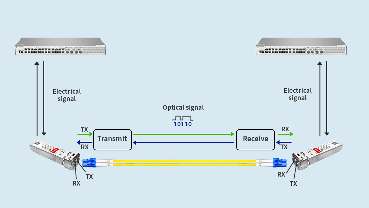
SFP 10G ER works by converting 10Gbps electrical Ethernet signals into 1550nm optical signals for transmission over single-mode fiber up to 40km, and then converting the received optical signals back into electrical signals at the destination device. Its extended reach capability is achieved through higher transmit optical power, optimized receiver sensitivity, and operation in the low-attenuation 1550nm window.
Understanding its transmission mechanism and link budget principles is essential for proper network design.
Optical Transmission Mechanism
SFP 10G ER transmits data by using a 1550nm laser source combined with high-speed modulation to encode digital signals onto an optical carrier.
The transmission process follows these steps:
-
The host device sends a 10Gbps differential electrical signal to the SFP+ module.
-
The module’s laser driver modulates a 1550nm laser source according to the incoming data stream.
-
The optical signal is launched into single-mode fiber through the LC duplex interface.
-
At the receiving end, a photodiode converts the optical signal back into an electrical signal.
-
The signal is amplified and reshaped before being sent to the host device.
The use of 1550nm is critical because single-mode fiber exhibits lower attenuation in this wavelength range compared to 1310nm, enabling longer transmission distances without amplification.
In addition, ER modules are designed with:
-
Higher transmit optical output power than LR
-
Improved receiver sensitivity
-
Tight compliance with 10GBASE-ER optical masks
These characteristics collectively enable stable 40km operation.
Link Budget and Distance Planning
SFP 10G ER supports 40km transmission because its optical power budget compensates for fiber attenuation, connector loss, and splice loss within that span.
A simplified link budget concept can be expressed as:
Optical Power Budget = Transmit Power − Receiver Sensitivity
A typical engineering planning view looks like this:
| Parameter |
Typical Range |
Purpose |
| Transmit Power |
High output (ER class) |
Compensate long fiber loss |
| Receiver Sensitivity |
Enhanced |
Detect weak signals |
| Fiber Attenuation |
~0.25dB/km at 1550nm |
Distance-dependent loss |
| Maximum Reach |
40km |
Standardized limit |
For example:
-
40km × ~0.25dB/km ≈ 10dB fiber loss
-
Add connector and splice losses (typically 1–2dB)
-
Total link loss must remain within the module’s optical budget
When planning a 10G ER link, engineers must consider:
If total attenuation exceeds the available optical budget, the link may experience high bit error rates or fail to establish entirely.
By combining higher optical output, operation at 1550nm, and defined receiver thresholds, SFP 10G ER achieves reliable extended-reach Ethernet transmission within standardized 40km limits without requiring optical amplifiers or dispersion compensation modules in typical metro scenarios.
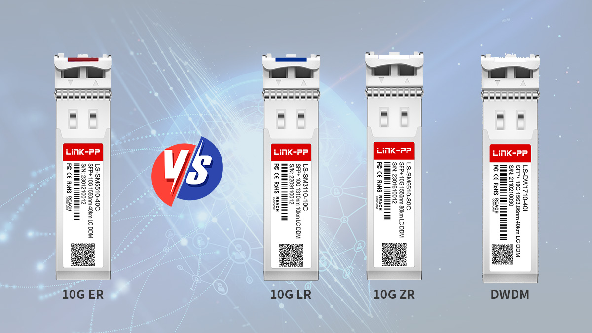
⏩ SFP 10G ER vs Other 10G Optical Modules
SFP 10G ER is designed for 40km single-mode transmission at 1550nm, making it suitable for extended metro and long campus links. Compared with other 10G optical modules such as LR, ZR, and SR, it occupies the middle ground between medium-reach and ultra-long-reach 10G Ethernet solutions.
Selecting the correct 10G module depends primarily on distance, fiber type, optical budget requirements, and cost considerations.
SFP 10G ER vs 10G LR
SFP 10G ER supports up to 40km over single-mode fiber, while 10G LR is limited to 10km at 1310nm. ER is used when link distance exceeds the 10km threshold but does not require ZR-level reach.
| Parameter |
10G LR |
10G ER |
| Maximum Reach |
10km |
40km |
| Wavelength |
1310nm |
1550nm |
| Fiber Type |
Single-mode |
Single-mode |
| Optical Budget |
Moderate |
Higher |
Key engineering differences:
-
ER operates at 1550nm, where fiber attenuation is lower.
-
ER provides higher transmit optical power and stronger receiver sensitivity.
-
Power consumption of ER is typically higher than LR.
Decision logic:
If a link is close to 10km but includes multiple patch panels or splices, ER may be selected to provide additional optical margin.
SFP 10G ER vs 10G ZR
SFP 10G ER supports 40km transmission, while 10G ZR typically supports 80km reach under controlled fiber conditions.
| Parameter |
10G ER |
10G ZR |
| Maximum Reach |
40km |
80km |
| Wavelength |
1550nm |
1550nm |
| Optical Output |
High |
Very high |
| Typical Use |
Metro links |
Long metro / edge long-haul |
Technical considerations:
-
ZR modules operate closer to dispersion and attenuation limits.
-
Chromatic dispersion becomes more significant at 80km.
-
ZR modules often consume more power than ER.
Selection guideline:
For distances beyond 80km, optical transport systems or DWDM solutions are typically required.
ER vs SR
Although both operate at 10Gbps, ER and SR serve fundamentally different environments.
| Parameter |
10G SR |
10G ER |
| Maximum Reach |
300m |
40km |
| Wavelength |
850nm |
1550nm |
| Fiber Type |
Multimode |
Single-mode |
| Deployment Type |
Data center |
Metro / campus backbone |
SR is optimized for short-reach multimode fiber inside data centers. ER is optimized for long single-mode links across buildings or metro areas.
The difference is not incremental but architectural:
ER vs DWDM Solutions
SFP 10G ER operates on a fixed wavelength and supports point-to-point transmission up to 40km without multiplexing. DWDM solutions enable multiple wavelengths over a single fiber pair for higher aggregate capacity.
Key distinction:
-
ER is suitable for single-wavelength, moderate-distance links.
-
DWDM is used when fiber scarcity or capacity scaling is the primary concern.
Decision factors:
If only a single 10Gbps link is required over ≤40km, ER provides a simpler architecture. If multiple 10Gbps channels must coexist on the same fiber, DWDM becomes necessary.
📍 In summary, SFP 10G ER fills the gap between 10G LR (10km) and 10G ZR (80km), delivering standardized 40km transmission over single-mode fiber while maintaining SFP+ compatibility and manageable power consumption for metro-scale deployments.
⏩ Typical Applications of SFP 10G ER
SFP 10G ER is primarily used in 10Gbps networks that require stable transmission up to 40km over single-mode fiber. It is commonly deployed in metro, campus backbone, and medium-range inter-site connectivity scenarios where LR modules cannot meet distance requirements but DWDM systems are not justified.
Its application is distance-driven rather than density-driven, making it suitable for structured long-span Ethernet links.
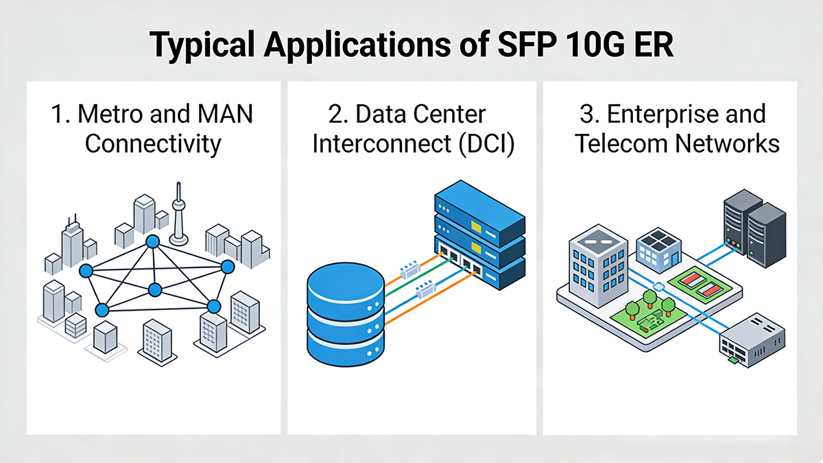
Metro and MAN Connectivity
SFP 10G ER is widely used in Metropolitan Area Networks (MAN) to interconnect aggregation nodes, access rings, and distribution sites within a 40km radius.
Typical deployment scenarios include:
-
Inter-building fiber links across a city
-
ISP aggregation node connectivity
-
Government and utility network backbones
-
Campus-to-campus fiber interconnect
Why ER is appropriate in metro environments:
-
1550nm operation reduces attenuation over longer spans
-
Higher optical budget compensates for patch panels and splices
-
No need for optical amplifiers within 40km
In metro topologies where fiber routes include multiple intermediate distribution frames, ER provides additional optical margin compared to LR, reducing risk of link instability.
Data Center Interconnect (DCI)
SFP 10G ER is suitable for medium-range data center interconnect scenarios where facilities are geographically separated but remain within 40km fiber distance.
Common DCI use cases:
-
Primary to secondary data center links
-
Active-active redundancy between sites
-
Disaster recovery network replication
-
Core-to-edge data center connectivity
Unlike short-reach SR modules used inside a data center, ER modules support inter-facility links over leased dark fiber or enterprise-owned fiber infrastructure.
Engineering considerations in DCI:
-
Validate total fiber attenuation
-
Confirm link margin with DOM readings
-
Ensure compatible optical power levels on both ends
When distance exceeds typical campus range but remains within metro scale, ER becomes a practical 10G Ethernet transport method without introducing transport-layer complexity.
Enterprise and Telecom Networks
In enterprise and telecom networks, SFP 10G ER is deployed for long uplinks and backbone segments where 10Gbps capacity is required across dispersed locations.
Typical enterprise use cases:
-
Headquarters to branch office backbone
-
Long-distance core switch uplinks
-
Surveillance network backbone over single-mode fiber
-
Industrial site interconnect
Telecom-related scenarios:
Deployment logic in these environments often follows:
-
Fiber distance exceeds 10km.
-
Existing infrastructure uses single-mode fiber.
-
No wavelength multiplexing system is required.
-
10Gbps bandwidth is sufficient for traffic demand.
Because SFP 10G ER remains within standardized Ethernet architecture, it integrates directly into switches and routers without requiring external optical transport equipment.
📍 In practical network design, SFP 10G ER is selected whenever the link distance falls between 10km and 40km and a single 10Gbps Ethernet channel over single-mode fiber meets performance and capacity requirements.
⏩ Cabling and Deployment Guidelines
SFP 10G ER requires OS2 single-mode fiber, clean LC duplex connectors, and proper link budget validation to ensure stable 40km transmission at 1550nm. Because ER operates with higher optical power and tighter margins than shorter-reach modules, fiber quality and installation practices directly impact link reliability.
Correct cabling and disciplined deployment procedures are essential for preventing excessive attenuation and signal degradation.
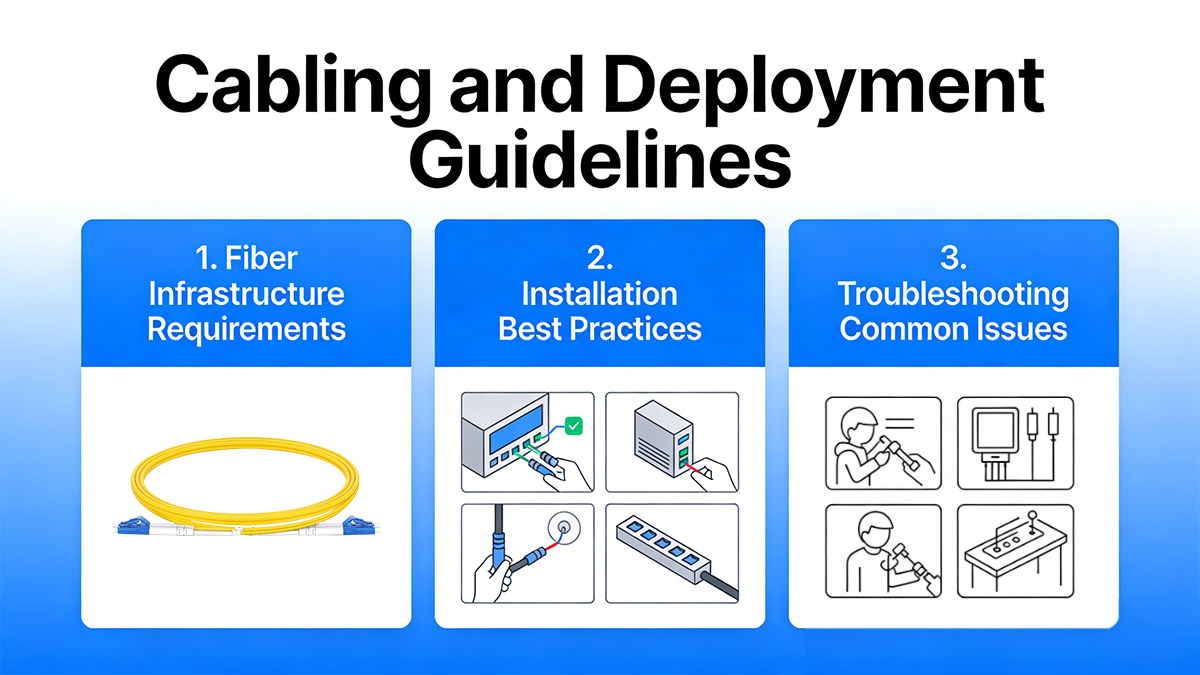
Fiber Infrastructure Requirements
SFP 10G ER is designed specifically for single-mode fiber and should not be used with multimode fiber.
| Parameter |
Requirement |
Notes |
| Fiber Type |
OS2 single-mode |
Low attenuation at 1550nm |
| Wavelength |
1550nm |
Optimized transmission window |
| Typical Attenuation |
~0.25dB/km |
At 1550nm |
| Connector Type |
LC duplex |
UPC recommended |
Key infrastructure considerations:
-
Use OS2 fiber to ensure low attenuation over long distances
-
Minimize the number of patch panels and intermediate distribution frames
-
Keep splice losses within acceptable thresholds
-
Maintain consistent connector polishing type (typically UPC)
Even small connector contamination can introduce 0.5–1dB of additional loss, which becomes significant in long-span links approaching 40km.
Installation Best Practices
Proper installation ensures that the available optical power budget is not compromised.
Recommended deployment steps:
-
Inspect and clean all LC connectors before insertion.
-
Verify fiber polarity to prevent transmit/receive mismatch.
-
Insert the SFP+ module firmly until latch engagement.
-
Confirm link establishment at 10Gbps on the host device.
-
Check DOM readings for transmit power and receive power levels.
Operational best practices:
-
Avoid tight fiber bends (respect minimum bend radius).
-
Do not exceed the rated temperature range.
-
Use optical power meters for long-span validation.
Because ER modules operate at higher transmit power than LR transceiver, verifying that received optical power does not exceed the maximum input threshold is also important, especially in shorter-than-expected fiber runs.
Troubleshooting Common Issues
When an SFP 10G ER link fails or shows instability, root causes typically relate to attenuation, contamination, or configuration mismatch.
Common issues and checks:
-
Link not coming up
-
Low receive optical power
-
Inspect and clean connectors
-
Measure total fiber attenuation
-
Check for excessive splices or damaged fiber
-
High bit error rate (BER)
-
Review DOM optical power levels
-
Confirm link margin (target safety margin ≥2dB)
-
Evaluate environmental temperature stability
-
Interoperability concerns
In long-distance deployments, even small incremental losses accumulate. Maintaining strict fiber hygiene, accurate attenuation calculations, and DOM monitoring ensures stable 10Gbps performance across extended 40km spans.
Proper cabling discipline combined with link budget verification is the primary factor determining the long-term stability of SFP 10G ER deployments.
⏩ Compatibility and Interoperability
SFP 10G ER modules are interoperable across platforms that support 10GBASE-ER and SFP+ interfaces, provided electrical, optical, and firmware compatibility requirements are met. Although the 10GBASE-ER standard defines physical layer behavior, vendor implementation details such as EEPROM coding and firmware validation can influence practical interoperability.
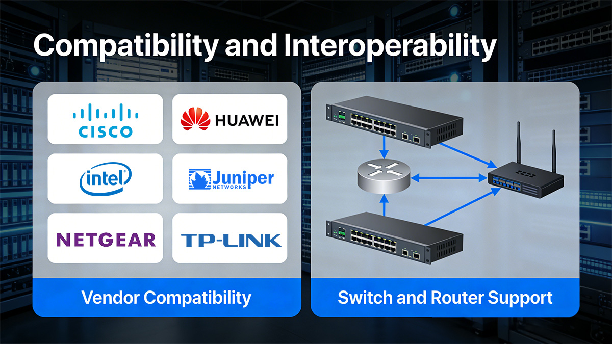
Understanding compatibility factors prevents link failures and device rejection issues during deployment.
Vendor Compatibility
SFP 10G ER modules must match the host device’s firmware expectations, even when they comply with IEEE 10GBASE-ER specifications.
Core compatibility factors include:
While 10GBASE-ER optical parameters are standardized under IEEE 802.3ae, many switch and router vendors implement firmware-level checks that validate:
-
Vendor name
-
Part number
-
Transceiver type
-
Power class
If the module’s coding does not match platform expectations, the device may:
-
Disable the port
-
Generate warning logs
-
Limit functionality
To ensure interoperability:
-
Confirm the module is coded for the target switch or router platform.
-
Verify firmware version compatibility.
-
Validate DOM readings after installation.
-
Perform cross-vendor interoperability testing when mixing brands.
Standards compliance ensures physical signal compatibility, but firmware-level validation determines operational acceptance.
Switch and Router Support
SFP 10G ER modules require SFP+ ports that explicitly support 10G operation and extended-reach optics.
Before deployment, verify:
-
The port supports 10Gbps SFP+ operation.
-
The platform firmware includes 10GBASE-ER optical profiles.
-
Maximum transceiver power class is supported.
-
DOM monitoring is enabled for diagnostics.
Typical configuration considerations:
-
Force port speed to 10Gbps if auto-negotiation is not supported.
-
Disable incompatible Ethernet features if required.
-
Confirm no port-level optical power restrictions apply.
In high-density switches, power budget limitations per slot or per line card may also affect compatibility, especially since ER modules typically consume more power than LR variants.
Interoperability Between Different 10G Modules
SFP 10G ER can interoperate with another 10GBASE-ER module on the opposite end of a link. However, interoperability with LR or ZR modules is conditional.
Engineering rules:
-
ER ↔ ER: Fully interoperable within 40km specification
-
ER ↔ LR: May work only within LR optical budget constraints
-
ER ↔ ZR: Possible if optical power and dispersion conditions align
When mixing different reach classes:
-
Confirm transmit optical power does not overload the receiver.
-
Ensure total attenuation remains within the lower-budget module’s tolerance.
-
Validate DOM readings on both ends.
Because ER operates at 1550nm and LR at 1310nm, direct interoperability between ER and LR is generally not feasible due to wavelength mismatch.
📍 Key Takeaways: In practical deployments, SFP 10G ER interoperability depends on three layers:
-
IEEE 10GBASE-ER optical compliance
-
SFP+ electrical and mechanical compatibility
-
Vendor firmware acceptance
Ensuring alignment across all three layers guarantees stable, standards-compliant 10Gbps long-distance connectivity.
⏩ Advantages and Limitations of SFP 10G ER
SFP 10G ER provides standardized 40km transmission over single-mode fiber at 1550nm, offering extended reach without requiring DWDM systems. However, its higher optical power and longer reach also introduce cost, power, and engineering considerations compared to shorter-reach modules.
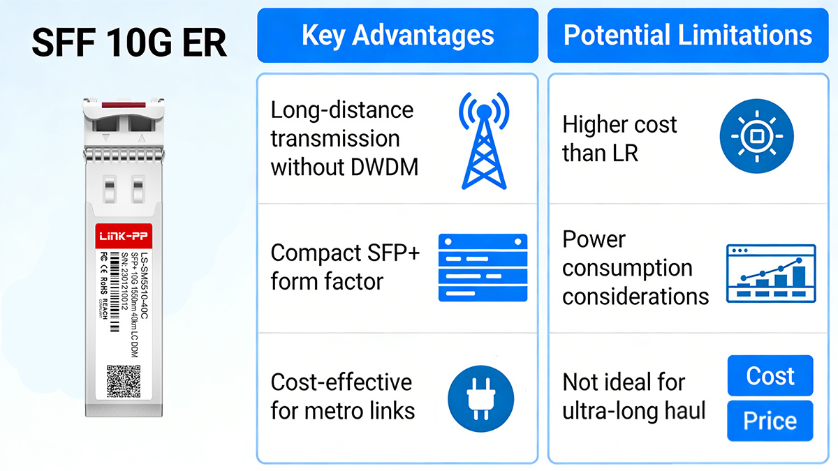
Understanding both advantages and constraints ensures appropriate deployment decisions.
Key Advantages
SFP 10G ER enables long-distance 10Gbps Ethernet connectivity within a compact SFP+ form factor.
| Advantage |
Technical Impact |
Deployment Value |
| 40km Reach |
High optical budget |
Metro-scale connectivity |
| 1550nm Operation |
Lower fiber attenuation |
Stable long spans |
| SFP+ Form Factor |
Hot-pluggable |
High port density |
| IEEE Compliance |
10GBASE-ER standard |
Multi-vendor support |
Primary benefits include:
-
Supports up to 40km without optical amplification
-
Operates in the low-loss 1550nm window
-
Integrates directly into standard SFP+ ports
-
Avoids complexity of DWDM systems for single-channel links
From an engineering perspective, ER provides additional link margin compared to LR modules, which can be critical in fiber routes with multiple connectors or aging infrastructure.
It also simplifies network architecture when only a single 10Gbps wavelength is required between sites.
Potential Limitations
While SFP 10G ER extends reach significantly beyond LR, it is not optimized for every environment.
| Limitation |
Technical Reason |
Practical Impact |
| Higher Cost |
Stronger laser components |
Increased CapEx |
| Higher Power Consumption |
Higher optical output |
Thermal planning required |
| Single Wavelength |
No multiplexing |
Limited scalability |
| 40km Limit |
Optical budget ceiling |
Not for long-haul |
Key constraints include:
-
Higher transmit power increases module cost relative to LR
-
Greater power consumption may impact dense switch environments
-
Not suitable for links exceeding 40km without optical transport systems
-
Does not provide wavelength multiplexing capability
Additionally, at 1550nm over long distances, chromatic dispersion becomes more relevant than in 1310nm LR deployments. While manageable within 40km limits, dispersion considerations grow as span distance approaches maximum specification.
⏩ How to Choose the Right SFP 10G ER Module
Choosing the right SFP 10G ER module requires validating fiber distance, optical loss, compatibility, and environmental conditions. Because ER modules operate close to defined optical budget limits for 40km transmission, proper technical evaluation ensures stable 10Gbps performance and prevents deployment risks.
Selection should follow a structured engineering approach rather than relying solely on nominal reach specifications.
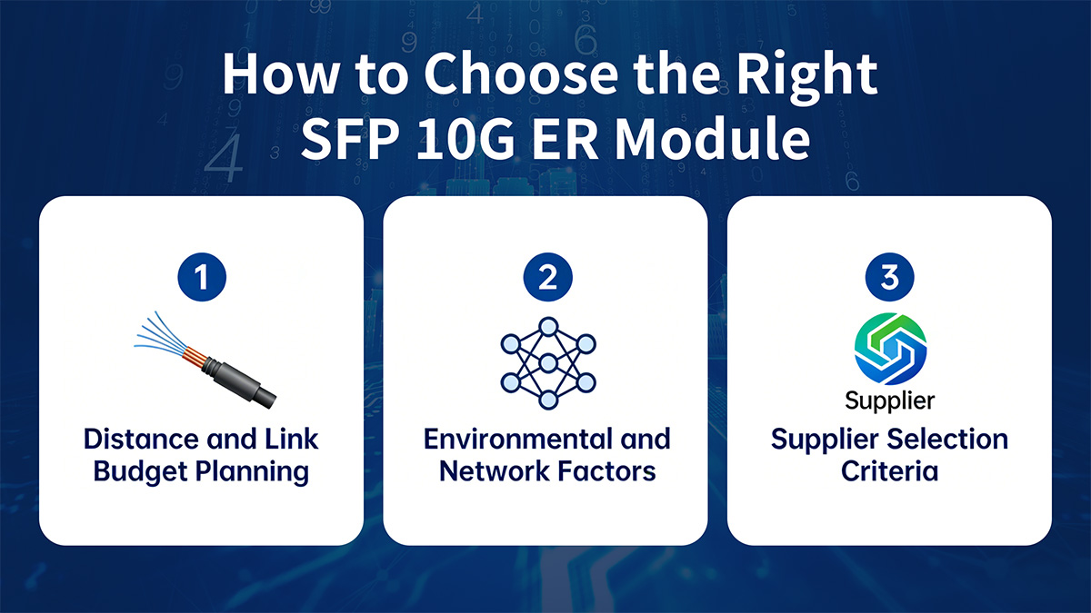
Distance and Link Budget Planning
The first step is confirming that total link attenuation falls within the optical budget of the SFP 10G ER module.
| Parameter |
Typical Value |
Planning Purpose |
| Maximum Reach |
40km |
Standard limit |
| Fiber Attenuation |
~0.25dB/km @1550nm |
Distance loss calculation |
| Connector/Splice Loss |
0.2–0.5dB per event |
Cumulative loss |
| Safety Margin |
≥2dB recommended |
Stability buffer |
Engineering process:
-
Measure actual fiber distance (not just map estimate).
-
Calculate fiber attenuation (distance × attenuation/km).
-
Add connector and splice losses.
-
Compare total loss to module optical budget.
-
Reserve at least 2dB safety margin.
If total attenuation approaches the upper limit of the ER optical budget, long-term stability may be affected by temperature variation and aging fiber.
For shorter links (e.g., 15–20km), verify that received optical power does not exceed maximum input thresholds, especially in low-loss fiber routes.
Environmental and Network Factors
SFP 10G ER modules must operate within specified environmental and electrical constraints.
Selection considerations include:
In high-density switches, cumulative transceiver power draw may affect thermal performance. Ensure chassis airflow and cooling design can handle ER modules, which typically consume more power than LR optics.
Supplier and Quality Considerations
Optical performance consistency is critical for long-distance modules.
When evaluating suppliers:
-
Verify compliance testing reports (10GBASE-ER optical mask).
-
Confirm real optical power testing, not simulation-only validation.
-
Check compatibility testing across mainstream switch platforms.
-
Review warranty terms and technical support capability.
Because ER modules operate at higher optical power and tighter margins than LR, manufacturing tolerance and quality control directly influence link reliability.
⏩ FAQs About SFP 10G ER
What distance does SFP 10G ER support?
SFP 10G ER supports transmission up to 40km over OS2 single-mode fiber at 1550nm. Actual achievable distance depends on total link attenuation, connector loss, and maintaining sufficient optical margin within the defined 10GBASE-ER power budget.
What wavelength does SFP 10G ER use?
SFP 10G ER operates at 1550nm, which is optimized for low attenuation in single-mode fiber. This wavelength enables extended reach compared to 1310nm-based LR modules.
Can SFP 10G ER work with 10G LR modules?
No, SFP 10G ER typically cannot interoperate directly with 10G LR modules because they operate at different wavelengths (1550nm vs 1310nm). Both ends of the link should use 10GBASE-ER optics for proper signal compatibility.
Does SFP 10G ER require single-mode fiber?
Yes, SFP 10G ER requires single-mode fiber (typically OS2). It is not designed for multimode fiber and will not function correctly in multimode environments.
Does SFP 10G ER require optical amplifiers?
No, SFP 10G ER does not require optical amplifiers for distances up to 40km, provided the total link attenuation remains within the module’s optical power budget.
What should be checked before deploying SFP 10G ER?
Before deployment, verify fiber distance, calculate total attenuation, confirm switch compatibility, validate firmware support, and ensure proper connector cleanliness to maintain sufficient optical margin for stable 10Gbps operation.
⏩ Conclusion
SFP 10G ER is a standardized 10Gbps extended-reach optical transceiver that delivers reliable transmission up to 40km over single-mode fiber at 1550nm under 10GBASE-ER specifications defined by IEEE 802.3ae. It fills the critical gap between 10G LR (10km) and longer-reach transport optics, providing sufficient optical budget for metro, campus backbone, and medium-range data center interconnect deployments without requiring DWDM systems.
Successful deployment depends on accurate link budget calculation, proper fiber infrastructure, strict connector hygiene, and verified platform compatibility. When distance falls between 10km and 40km and a single 10Gbps Ethernet channel over single-mode fiber meets capacity requirements, SFP 10G ER remains a technically sound and standards-compliant choice.
For verified 10GBASE-ER compliant modules with tested compatibility and documented optical performance, you can explore available options through the LINK-PP Official Store to ensure stable and reliable 40km 10Gbps connectivity in your network.