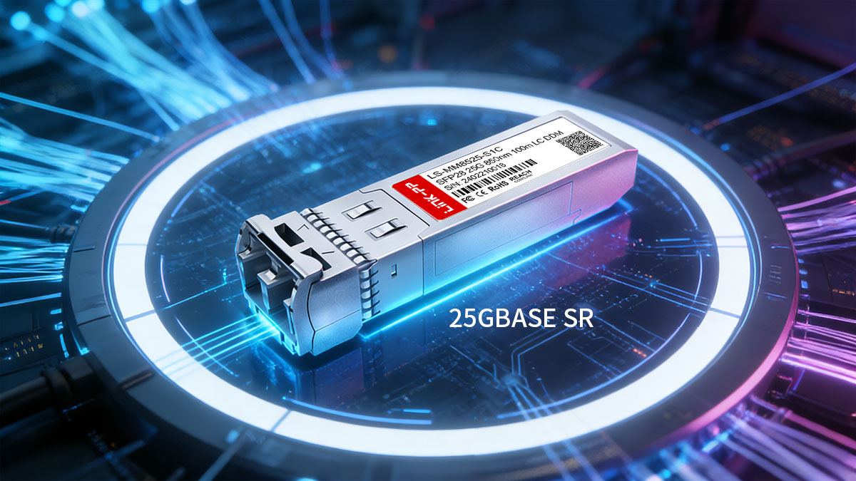
25GBASE SR has become the standard short-reach optical solution for modern 25Gbps Ethernet deployments, especially in high-density data centers and enterprise networks transitioning from 10G to 25G architectures. Designed for multimode fiber transmission over short distances, 25GBASE SR SFP28 transceiver delivers higher bandwidth per lane, improved power efficiency, and scalable migration paths toward 100G spine-leaf infrastructures.
As server port speeds increase and virtualization workloads intensify, network planners are prioritizing solutions that balance performance, compatibility, and infrastructure reuse. 25GBASE SR modules operate at 850nm over OM3, OM4, or OM5 multimode fiber, making them particularly suitable for Top-of-Rack to Leaf switch links and short-distance aggregation scenarios where cost control and port density matter.
This guide provides a structured, technically detailed overview of 25GBASE SR transceivers — including specifications, compatibility considerations, deployment scenarios, and selection criteria — to help ensure reliable 25Gbps short-reach connectivity in modern network environments.
🔳 What Is 25GBASE SR?
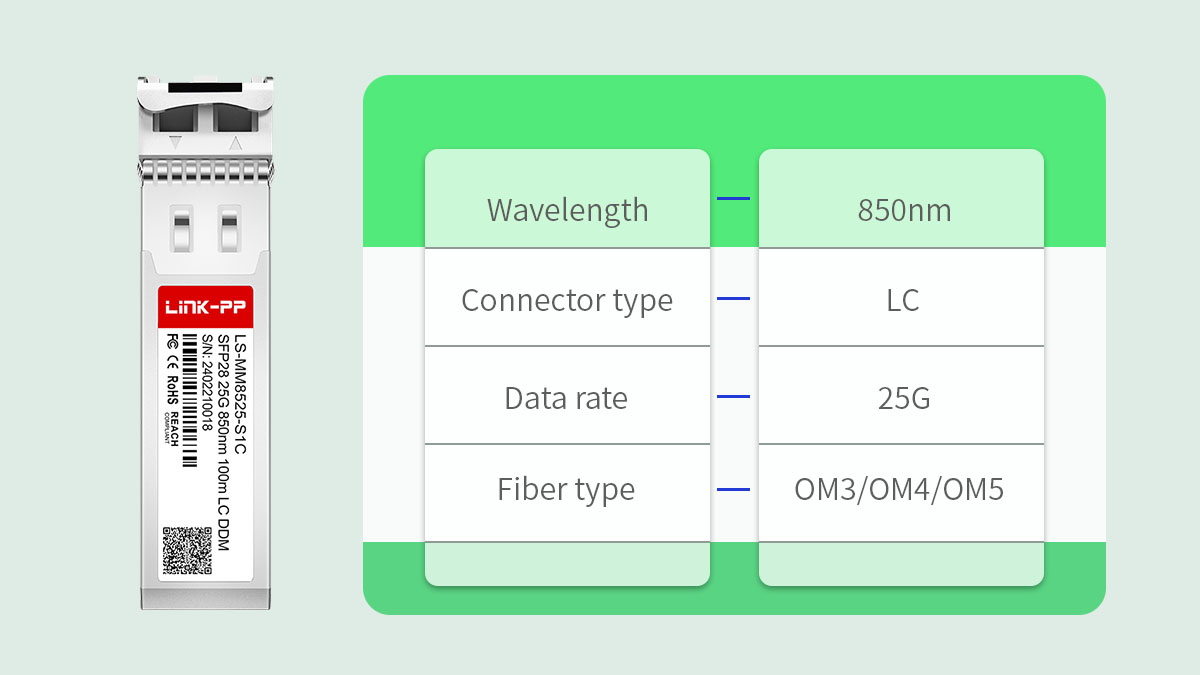
25GBASE SR is a short-reach 25Gbps Ethernet optical standard designed for multimode fiber transmission within data centers and enterprise networks. It operates over 850nm wavelength using SFP28 form factor modules and is optimized for high-density, short-distance links such as server-to-switch and switch-to-switch connections.
Defined under the IEEE 802.3by standard, 25GBASE SR enables single-lane 25Gbps transmission, improving bandwidth efficiency compared to legacy 10G solutions while maintaining similar cabling infrastructure in many cases.
Optical and Interface Characteristics
25GBASE SR modules use 850nm VCSEL technology and duplex LC interfaces to transmit 25Gbps over multimode fiber.
| Parameter |
Value |
Notes |
| Data Rate |
25Gbps |
Single-lane transmission |
| Wavelength |
850nm |
VCSEL-based |
| Connector |
Duplex LC |
Multimode fiber |
| Fiber Type |
OM3 / OM4 / OM5 |
Multimode only |
| Form Factor |
SFP28 |
Hot-pluggable |
The use of VCSEL (Vertical-Cavity Surface-Emitting Laser) technology enables lower power consumption and cost efficiency compared to long-reach single-mode optics. The SFP28 form factor maintains the same physical dimensions as SFP+, allowing higher port density in modern switches.
Transmission Distance and Fiber Compatibility
25GBASE SR is designed for short distances, typically up to 70m on OM3 and 100m on OM4 multimode fiber.
| Fiber Type |
Maximum Distance |
Deployment Scenario |
| OM3 |
70m |
Rack-level connectivity |
| OM4 |
100m |
Row-level connectivity |
| OM5 |
100m+ |
Extended multimode optimization |
Actual achievable distance depends on total link loss, connector quality, patch panel insertion loss, and environmental conditions. In structured cabling environments, link budget verification is recommended before deployment.
Position in 25G Network Architectures
25GBASE SR serves as the primary short-reach optical layer in 25G server access networks and spine-leaf topologies.
It is commonly used for:
-
25G server NIC to Top-of-Rack switch links
-
Leaf to spine short-range interconnects
-
Storage and high-throughput virtualization clusters
-
Migration projects replacing 10G SFP+ with 25G SFP28
Because it uses single-lane 25Gbps transmission, 25GBASE SR provides better spectral efficiency than 10G and serves as a building block for 100G (4×25G) breakout configurations.
🔳 Key Specifications of 25GBASE SR Modules
The core specifications of 25GBASE SR modules define their transmission capability, compatibility scope, and deployment limits. Understanding optical parameters, performance characteristics, and monitoring functions is essential for selecting suitable 25G SFP28 SR transceivers in structured cabling environments.
Below is a structured breakdown of the most important technical specifications.
Optical and Interface Specifications
25GBASE SR modules operate at 25Gbps using 850nm VCSEL lasers in the SFP28 form factor with duplex LC connectivity.
| Parameter |
Typical Value |
Technical Notes |
| Data Rate |
25Gbps |
Single electrical lane |
| Wavelength |
850nm |
VCSEL light source |
| Connector |
Duplex LC |
Multimode interface |
| Form Factor |
SFP28 |
Same size as SFP+ |
| Power Consumption |
<1.5W (typical) |
Vendor dependent |
The 850nm wavelength is optimized for multimode fiber transmission, offering efficient short-reach performance with relatively low power draw. The SFP28 interface supports higher signal integrity requirements than SFP+, enabling reliable 25Gbps signaling.
Because SFP28 shares the same physical dimensions as SFP+, it allows:
-
Increased switch port density
-
Backward mechanical compatibility
-
Efficient airflow design in high-density racks
However, electrical compatibility depends on switch chipset support.
Performance and Transmission Distance
25GBASE SR supports short-reach transmission up to 100m, depending on fiber grade and total link loss.
| Fiber Type |
Maximum Reach |
Typical Use Case |
| OM3 |
70m |
Rack-to-rack |
| OM4 |
100m |
Row-level |
| OM5 |
100m+ (optimized) |
Advanced MMF deployments |
Performance is influenced by:
-
Total insertion loss (connectors + patch panels)
-
Fiber modal bandwidth
-
Transmit optical power and receiver sensitivity
-
Environmental temperature conditions
In structured cabling systems with multiple cross-connects, link budget calculation is recommended. Exceeding allowable loss margins can lead to increased bit error rate (BER) even within nominal distance limits.
Compared to 10GBASE SR, 25GBASE SR requires stricter signal integrity due to higher data rates, making fiber quality and connector cleanliness more critical.
Digital Diagnostics Monitoring (DDM)
Most 25GBASE SR modules support Digital Diagnostics Monitoring (DDM), enabling real-time operational visibility.
DDM provides monitoring for:
-
Module temperature
-
Supply voltage
-
Transmit optical power
-
Receive optical power
-
Laser bias current
This functionality allows network operators to:
-
Detect abnormal optical degradation early
-
Identify overheating risks in dense deployments
-
Monitor optical power drift over time
-
Perform proactive maintenance
In high-density data centers, DDM becomes particularly important for large-scale rollouts, where centralized monitoring systems rely on transceiver telemetry for operational stability.
🔳 Common Use Cases for 25GBASE SR
25GBASE SR is primarily deployed for high-density short-reach 25Gbps connectivity inside data centers and enterprise environments. Its multimode design, low latency characteristics, and compatibility with SFP28 switching platforms make it ideal for server access and aggregation scenarios where distances typically remain under 100m.
Below are the most common deployment environments.
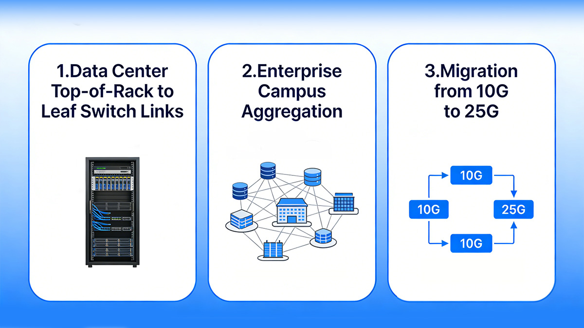
Data Center Top-of-Rack to Leaf Switch Links
The most typical use case for 25GBASE SR is server-to-ToR and leaf-layer connectivity in spine-leaf architecture.
In modern data centers:
-
Servers are equipped with 25G NICs.
-
ToR switches aggregate multiple 25G server links.
-
Leaf switches connect upward to spine switches via 100G uplinks (4×25G lanes).
Why 25GBASE SR fits this architecture:
-
Supports high port density in SFP28-based switches
-
Low power consumption compared to long-reach optics
-
Optimized for rack-level (<70m) and row-level (<100m) distances
-
Seamless integration into 100G breakout designs
This structure allows efficient east-west traffic handling, which dominates virtualized and containerized workloads.
Enterprise Campus Aggregation
25GBASE SR is also suitable for short-distance aggregation links inside enterprise server rooms or campus core networks.
Typical scenarios include:
-
Access layer switch uplinks within the same building
-
High-speed connections between core switches in small server rooms
-
Virtual desktop infrastructure (VDI) clusters
-
Storage area network (SAN) short-range interconnects
Compared to legacy 10G links, 25GBASE SR offers:
-
2.5× bandwidth increase per port
-
Improved scalability without major fiber replacement
-
Reduced cost per gigabit in high-density deployments
For organizations upgrading internal infrastructure without moving to single-mode fiber, 25G multimode optics provide a balanced transition path.
Migration from 10G to 25G
25GBASE SR is commonly deployed as a direct upgrade path from 10GBASE SR in multimode environments.
When migrating from 10G:
-
Existing OM3/OM4 fiber can often be reused.
-
Switches are replaced or upgraded to SFP28-capable platforms.
-
Servers are equipped with 25G NICs.
-
Uplinks transition to 100G (4×25G architecture).
Upgrade comparison:
| Feature |
10GBASE SR |
25GBASE SR |
| Data Rate |
10Gbps |
25Gbps |
| Fiber Type |
OM3/OM4 |
OM3/OM4/OM5 |
| Typical Reach (OM4) |
400m |
100m |
| Electrical Lanes |
1×10G |
1×25G |
Although 10GBASE SR supports longer multimode reach, 25GBASE SR delivers significantly higher bandwidth per lane, which improves switch port utilization and reduces oversubscription ratios.
Key migration considerations:
-
Verify fiber quality for higher signaling requirements
-
Confirm switch ASIC support for SFP28
-
Ensure compatibility coding for vendor platforms
📢 In summary, 25GBASE SR is most widely used in data center rack-level connectivity, enterprise aggregation, and 10G-to-25G upgrade projects, where short-reach multimode fiber infrastructure aligns with modern 25Gbps Ethernet design principles.
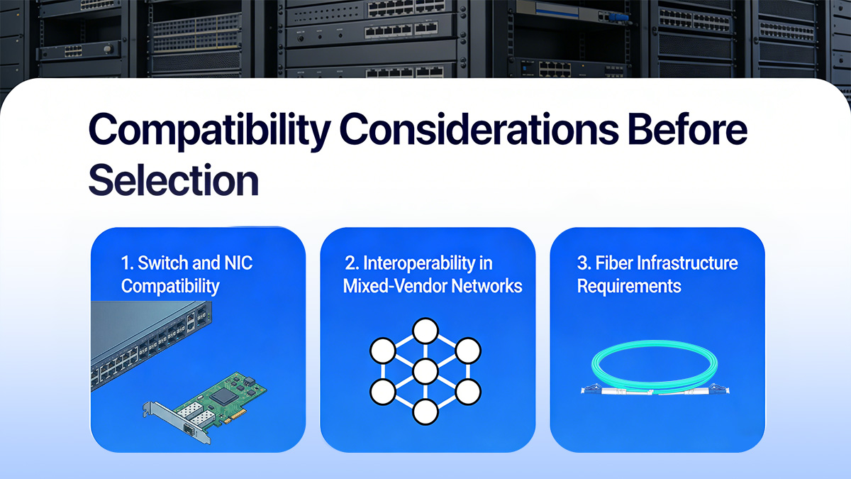
🔳 Compatibility Considerations Before Selection
Compatibility is the most critical factor when selecting a 25GBASE SR module, as optical, electrical, and firmware alignment directly determine link stability. Even if distance and fiber type match, incompatibility at the switch or NIC level can cause link failure, port shutdown, or performance degradation.
Before deployment, evaluate the following compatibility dimensions.
Switch and NIC Compatibility
25GBASE SR modules must be electrically and firmware-compatible with SFP28 ports on switches and network interface cards.
Although SFP28 shares the same physical size as SFP+, they are not automatically interchangeable.
Key compatibility checks:
-
Confirm the switch supports 25Gbps SFP28 ports (not SFP+ only).
-
Verify firmware version supports third-party or MSA-compliant optics.
-
Ensure the module EEPROM coding matches vendor requirements.
-
Check whether the port supports 1×25G mode (not breakout-only).
Compatibility comparison:
| Interface Type |
Supports 25GBASE SR |
Notes |
| SFP28 Port |
Yes |
Native 25G support |
| SFP+ Port |
No |
Limited to 10G |
| QSFP28 Breakout Port |
Yes (4×25G) |
Requires breakout cable |
Even though SFP28 modules may physically fit into SFP+ ports, they will not operate at 25Gbps unless the hardware supports it.
Interoperability in Mixed-Vendor Networks
In multi-vendor environments, interoperability validation is essential to prevent link negotiation issues.
Common risks include:
-
Vendor lock enforcement via firmware
-
Optical parameter mismatch
-
Inconsistent DOM/DDM reporting formats
-
Unexpected port-disable behavior
To minimize risk:
-
Use modules tested for specific switch models.
-
Verify IEEE 802.3by compliance.
-
Conduct lab validation before large-scale rollout.
-
Confirm cross-vendor link testing (e.g., Switch A to Switch B).
Interoperability becomes especially important in:
-
Data centers with mixed core and access vendors
-
Gradual infrastructure migration projects
-
Third-party optic deployments
Proper validation ensures stable link establishment and consistent performance monitoring.
Fiber Infrastructure Requirements
25GBASE SR performance depends heavily on multimode fiber quality and total link loss.
Fiber infrastructure evaluation should include:
-
Fiber grade verification (OM3, OM4, OM5)
-
Connector cleanliness and end-face inspection
-
Patch panel count and insertion loss measurement
-
Total link budget calculation
Fiber reach comparison:
| Fiber Type |
Typical Maximum Reach |
Deployment Risk Level |
| OM3 |
70m |
Moderate (shorter margin) |
| OM4 |
100m |
Low |
| OM5 |
100m+ optimized |
Low |
Additional considerations:
-
Excessive cross-connects reduce effective reach.
-
Dirty LC connectors increase insertion loss.
-
Older multimode fiber may not meet required modal bandwidth.
Because 25Gbps signaling is more sensitive than 10Gbps, marginal fiber infrastructure that worked for 10G may not guarantee stable 25G operation without verification.
📢 To sum up, evaluating switch support, vendor interoperability, and multimode fiber infrastructure is essential before selecting 25GBASE SR modules, ensuring stable 25Gbps short-reach connectivity without compatibility-related deployment risks.
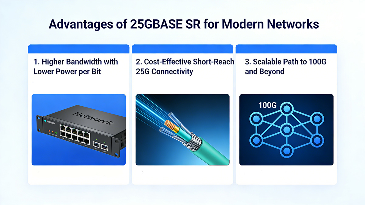
🔳 Advantages of 25GBASE SR for Modern Networks
25GBASE SR provides higher bandwidth density, improved power efficiency, and scalable architecture alignment for short-reach 25Gbps deployments. Compared to legacy 10G optics and longer-reach single mode transceivers, it offers a balanced combination of performance and infrastructure practicality in data center environments.
Below are the core advantages from an architectural and operational perspective.
Higher Bandwidth with Lower Power per Bit
25GBASE SR delivers 2.5× the bandwidth of 10GBASE SR while maintaining single-lane efficiency and controlled power consumption.
Because it transmits 25Gbps over a single electrical lane (instead of bonding multiple 10G lanes), it improves bandwidth density per switch ASIC port.
Bandwidth efficiency comparison:
| Metric |
10GBASE SR |
25GBASE SR |
| Data Rate |
10Gbps |
25Gbps |
| Electrical Lanes |
1×10G |
1×25G |
| Bandwidth per Port |
Baseline |
2.5× increase |
| Typical Power |
~1W |
<1.5W |
Although 25GBASE SR consumes slightly more power than 10G transceivers, the power per transmitted gigabit is lower, improving overall energy efficiency in high-density racks.
This is particularly beneficial in:
Cost-Effective Short-Reach 25G Connectivity
For short distances under 100m, 25GBASE SR remains more infrastructure-efficient than single-mode alternatives.
Key reasons:
-
Supports existing OM3/OM4 multimode fiber
-
Uses duplex LC patch cords (widely available)
-
Avoids the higher optical budget complexity of LR transceiver
-
Suitable for rack-level deployments without fiber overhaul
Cost-efficiency factors:
-
Lower fiber deployment cost compared to single-mode rollout
-
Reduced need for long-distance optical components
-
Simplified installation in structured cabling systems
In environments where most links remain inside the same row or adjacent racks, multimode 25G SR modules provide an optimal balance between performance and operational simplicity.
Scalable Path to 100G and Beyond
25GBASE SR serves as a foundational building block for 100G (4×25G) architectures in spine-leaf designs.
Modern data center designs commonly use:
Scalability model:
| Layer |
Typical Speed |
Role |
| Server Access |
25GBASE SR |
Edge connectivity |
| Leaf-Spine |
100G (4×25G) |
Aggregation |
| Core Expansion |
100G+ |
Backbone |
Because 100G QSFP28 uses four 25Gbps lanes internally, adopting 25GBASE SR at the access layer aligns naturally with higher-layer aggregation design.
This architectural consistency simplifies:
-
Network capacity planning
-
Port utilization optimization
-
Future bandwidth upgrades
It also reduces oversubscription ratios compared to 10G-based architectures, enabling more balanced traffic distribution.
🔳 Limitations and Deployment Considerations
While 25GBASE SR is highly efficient for short-reach 25Gbps connectivity, it is inherently limited by distance, multimode dependency, and environmental factors. Understanding these constraints ensures that deployments remain stable and aligned with network design goals.
Below are the key limitations and practical considerations.
Distance Constraints
25GBASE SR is strictly a short-reach solution and is not suitable for medium or long-distance links.
Maximum supported distances:
| Fiber Type |
Typical Maximum Reach |
Deployment Suitability |
| OM3 |
70m |
Rack-to-rack |
| OM4 |
100m |
Row-level |
| OM5 |
100m+ optimized |
Controlled environments |
Deployment implications:
-
Not suitable for building-to-building connections
-
Not recommended for metro or campus backbone links
-
Limited margin in high-loss structured cabling systems
Compared to single-mode LR modules, SR optics provide lower reach but reduced complexity and cost for short-distance applications. If link distances exceed 100m or include multiple cross-connect points, alternative optical standards should be evaluated.
Multimode Fiber Dependency
25GBASE SR requires multimode fiber infrastructure, which may limit long-term scalability compared to single-mode environments.
Key considerations:
-
OM3 fiber provides shorter margin at 25Gbps
-
Older multimode installations may not meet required modal bandwidth
-
Connector quality directly impacts link performance
Potential risks:
-
Higher bit error rate if insertion loss exceeds budget
-
Reduced distance capability in high-density patch environments
-
Performance degradation in poorly maintained fiber systems
Because 25Gbps signaling is more sensitive than 10Gbps, fiber plants previously sufficient for 10G may require validation before upgrading.
Thermal and Power Factors
In high-density switch environments, cumulative thermal output must be considered when deploying large volumes of 25GBASE SR modules.
Although individual modules typically consume less than 1.5W, aggregate power becomes relevant in:
-
48-port or 64-port SFP28 switches
-
High-density Top-of-Rack deployments
-
Enclosed rack designs with limited airflow
Thermal planning considerations:
-
Ensure adequate front-to-back airflow.
-
Avoid blocking ventilation with unmanaged cabling.
-
Monitor module temperature using DDM.
-
Verify switch power supply headroom.
Excessive operating temperatures can impact laser stability and shorten module lifespan. Proactive monitoring helps maintain long-term reliability.
🔳 How to Choose the Right 25GBASE SR Module
Selecting the right 25GBASE SR module requires aligning distance requirements, fiber type, platform compatibility, and deployment scale. A structured evaluation prevents interoperability issues and ensures stable 25Gbps short-reach performance.
Below is a practical decision framework.
Matching Distance and Fiber Type
The first selection criterion is confirming that your multimode fiber infrastructure supports the required transmission distance.
Distance alignment summary:
| Fiber Type |
Maximum Reach |
Recommendation |
| OM3 |
70m |
Suitable for rack-level links |
| OM4 |
100m |
Recommended for row-level deployments |
| OM5 |
100m+ optimized |
For advanced multimode environments |
Decision steps:
-
Measure actual cable route length (not straight-line distance).
-
Count patch panels and connectors in the path.
-
Estimate total insertion loss.
-
Verify margin against module link budget.
If distance approaches the upper limit of OM3, upgrading to OM4 patch cords may provide additional performance stability.
Evaluating Compatibility and Reliability
Platform compatibility and optical quality directly determine whether a 25GBASE SR module will operate reliably.
Compatibility checklist:
-
Confirm switch supports SFP28 25Gbps ports.
-
Verify firmware does not restrict third-party optics.
-
Ensure EEPROM coding matches platform requirements.
-
Check IEEE 802.3by compliance.
Reliability indicators:
-
Stable DDM telemetry reporting
-
Controlled transmit optical power levels
-
Consistent receiver sensitivity
-
Documented cross-vendor interoperability testing
Compatibility comparison:
| Factor |
Why It Matters |
Verification Method |
| Port Type |
Electrical support |
Switch datasheet |
| Firmware |
Vendor enforcement |
Release notes |
| Coding |
Port recognition |
Vendor testing |
| Standards |
Signal compliance |
IEEE reference |
Ignoring compatibility validation can result in port disablement or unstable link negotiation.
Considering Deployment Scale
Large-scale deployments require consistency, operational visibility, and lifecycle planning beyond single-link validation.
When planning broader rollouts:
-
Standardize on a tested module model.
-
Ensure consistent firmware revision across inventory.
-
Maintain spare stock alignment.
-
Integrate DDM monitoring into network management systems.
Scale-based considerations:
-
High-density racks amplify thermal factors.
-
Inventory consistency simplifies maintenance.
-
Standardized modules reduce operational complexity.
For data centers expanding toward 100G aggregation, ensuring 25GBASE SR alignment with future breakout configurations is also important for long-term scalability.
📢 In conclusion, choosing the right 25GBASE SR module involves validating fiber reach, confirming switch compatibility, and planning for deployment scale, ensuring reliable and efficient 25Gbps short-reach connectivity across modern network infrastructures.
🔳 Installation and Best Practices of 25GBASE SR
Proper installation and validation directly impact the stability and lifespan of 25GBASE SR links. Even when specifications and compatibility are correct, poor fiber handling or inadequate testing can lead to high error rates, intermittent link drops, or reduced optical margin.
Below are structured best practices for deploying 25G SFP28 SR modules in production environments.
Proper Fiber Handling
Clean and properly managed multimode fiber connections are essential for maintaining signal integrity at 25Gbps.
Because 25G signaling is more sensitive than 10G, contamination or micro-bending can significantly affect performance.
Recommended practices:
-
Inspect every LC connector end-face before insertion.
-
Clean connectors using approved fiber cleaning tools.
-
Avoid excessive bending radius (follow fiber manufacturer guidelines).
-
Label and organize patch cords to reduce strain.
-
Minimize unnecessary cross-connect points.
Common causes of link instability:
-
Dust or oil contamination on LC connectors
-
Loose or partially inserted connectors
-
High insertion loss from poor patch panel termination
-
Fiber exceeding recommended bend radius
Proactive inspection reduces troubleshooting time after deployment.
Testing and Validation
Every 25GBASE SR link should be validated with optical and logical testing before being placed into production.
Minimum validation steps:
-
Confirm link establishment at 25Gbps.
-
Check DDM readings (TX/RX optical power).
-
Verify optical power falls within normal operating range.
-
Monitor for CRC errors or packet drops.
-
Perform short-duration stress testing if possible.
Validation parameters:
| Test Item |
Expected Result |
Purpose |
| Link Status |
Up at 25Gbps |
Electrical compatibility |
| TX Power |
Within spec |
Laser stability |
| RX Power |
Within sensitivity range |
Link budget margin |
| Error Rate |
Zero or negligible |
Signal integrity |
If RX power is near the lower threshold, investigate insertion loss before scaling deployment.
Troubleshooting Common Issues
Most 25GBASE SR deployment issues stem from fiber contamination, compatibility mismatches, or marginal link budgets.
Systematic troubleshooting approach:
-
Verify port configuration (speed set to 25G).
-
Confirm module recognition in switch CLI.
-
Swap patch cords to rule out fiber defects.
-
Inspect and clean connectors.
-
Cross-test module in another port.
-
Compare DDM values between both ends.
Typical issue patterns:
-
Link down immediately → Likely compatibility or coding issue
-
Link up but high errors → Fiber loss or contamination
-
Intermittent link flaps → Thermal or marginal optical power
Using DDM diagnostics significantly accelerates root cause analysis, especially in high-density racks.
🔳 FAQs About 25GBASE SR
Q1: What is the maximum transmission distance of 25GBASE SR?
A: 25GBASE SR supports up to 70m on OM3 and up to 100m on OM4 multimode fiber under standard link conditions. Actual reach depends on insertion loss, connector count, and fiber quality.
Q2: Can a 25GBASE SR module operate in an SFP+ port?
A: No. 25GBASE SR requires an SFP28 port that supports 25Gbps signaling. Although the form factor is similar, SFP+ ports are limited to 10Gbps operation.
Q3: Is OM3 fiber adequate for 25GBASE SR deployments?
A: Yes, OM3 is supported, but the maximum recommended reach is approximately 70m. For longer short-reach links or improved margin, OM4 fiber provides better stability.
Q4: What type of connector does 25GBASE SR use?
A: 25GBASE SR uses duplex LC connectors and operates over multimode fiber (OM3/OM4/OM5).
Q5: Can 25GBASE SR connect to 100G QSFP28 ports?
A: Yes, when the 100G QSFP28 port is configured in 4×25G breakout mode. Each lane can support one independent 25GBASE SR link if the platform supports breakout functionality.
Q6: Does 25GBASE SR support Digital Diagnostics Monitoring (DDM)?
A: Most 25GBASE SR modules support DDM, allowing real-time monitoring of temperature, transmit/receive optical power, voltage, and laser bias current for proactive network maintenance.
🔳 Conclusion
25GBASE SR is the standardized short-reach 25Gbps multimode optical solution for modern data center and enterprise networks, delivering high port density, controlled power efficiency, and scalable alignment with 100G spine-leaf architectures. By carefully validating fiber type, transmission distance, switch compatibility, and deployment scale, organizations can ensure stable and future-ready 25G connectivity within rack-level and row-level environments.
For technically verified, compatibility-tested 25GBASE SR transceivers designed for reliable 25Gbps short-reach performance, explore the available solutions at the LINK-PP Official Store, where specifications and platform alignment are clearly documented to support structured network deployment.