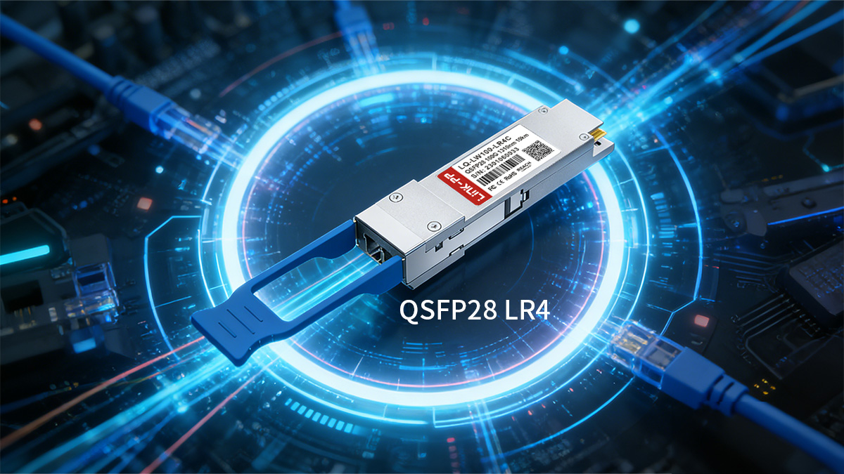
The 100G QSFP28 LR4 is one of the most widely deployed 100GbE single-mode optical module for medium-to-long distance links, supporting up to 10km transmission over duplex LC fiber. It is commonly used for data center interconnect (DCI), campus backbone, and aggregation layers where reliable 100G connectivity over single-mode infrastructure is required.
As 100G networks continue to replace 40G and 10G uplinks, LR4 modules play a key role in enabling scalable, long-reach connections without requiring complex DWDM systems. Compared with short-reach multimode optics such as SR4, the LR4 standard allows organizations to extend 100G links across buildings, between data halls, or across metro-scale enterprise environments using standard OS2 single-mode fiber.
This guide explains how 100G QSFP28 LR4 works, its core specifications, cabling requirements, deployment scenarios, and how it compares with other 100G optical standards such as CWDM4, PSM4, and DR1. The goal is to help network engineers and infrastructure planners determine when LR4 is the right choice, how to deploy it correctly, and what to consider when selecting compatible modules for production networks.
🔷 What Is a 100G QSFP28 LR4 Transceiver?
A 100G QSFP28 LR4 transceiver is a single-mode optical transceiver designed for 100GbE links up to 10km over duplex LC fiber. It converts four electrical 25Gbps lanes inside a switch or router into four optical wavelengths around 1310nm, multiplexes them onto one pair of single-mode fibers, and delivers reliable long-reach 100G connectivity without requiring DWDM transport systems.
Definition and Basic Function
The 100G QSFP28 LR4 module follows the IEEE 100GBASE-LR4 standard and is commonly used for medium-distance 100G connections between buildings, data halls, or aggregation layers.
Key characteristics:
- Form factor: QSFP28, hot-pluggable
- Transmission rate: 100Gbps (4×25Gbps)
- Fiber type: Single-mode fiber (OS2 recommended)
- Connector: Duplex LC
- Reach: Up to 10km
- Typical use: Switch-to-switch or router uplinks over SMF
In practical deployments, LR4 modules enable long-distance 100G connectivity using standard duplex fiber infrastructure rather than MPO parallel fiber systems.
How LR4 Technology Works
The LR4 standard uses four LAN-WDM wavelengths in the 1310nm range, each carrying a 25Gbps signal. Inside the module:
- Four electrical lanes enter the module from the switch ASIC
- Each lane is converted into an optical signal
- A multiplexer combines the four wavelengths
- The combined signal travels over one pair of SMF
- The receiving module demultiplexes and converts back to electrical
This wavelength-division approach allows LR4 to deliver long-reach performance while keeping fiber usage low (only two fibers required).
Most 100G LR4 links also rely on forward error correction (FEC) enabled on switches to maintain signal integrity across longer distances.
LR4 vs Other 100G Optical Standards
The LR4 module sits between short-reach and ultra-long-reach 100G optics in terms of distance and cost.
LR4 is typically chosen when 10km duplex SMF links are required without MPO cabling.
| Standard |
Fiber type |
Reach |
Typical use |
| 100G SR4 |
MMF (MPO) |
100m |
In-rack / short DC |
| 100G CWDM4 |
SMF LC |
2km |
Campus short SMF |
| 100G LR4 |
SMF LC |
10km |
Campus/DCI |
| 100G ER4 |
SMF LC |
40km |
Metro long reach |
In most enterprise and data center environments, LR4 becomes the practical choice when:
- Distance exceeds 2km
- Duplex LC SMF is available
- MPO infrastructure is not preferred
- Metro-scale links are needed but not 40km
This positioning makes the 100G QSFP28 LR4 one of the most versatile and commonly deployed long-reach 100G transceivers in modern networks.
🔷 Key Specifications of 100G QSFP28 LR4
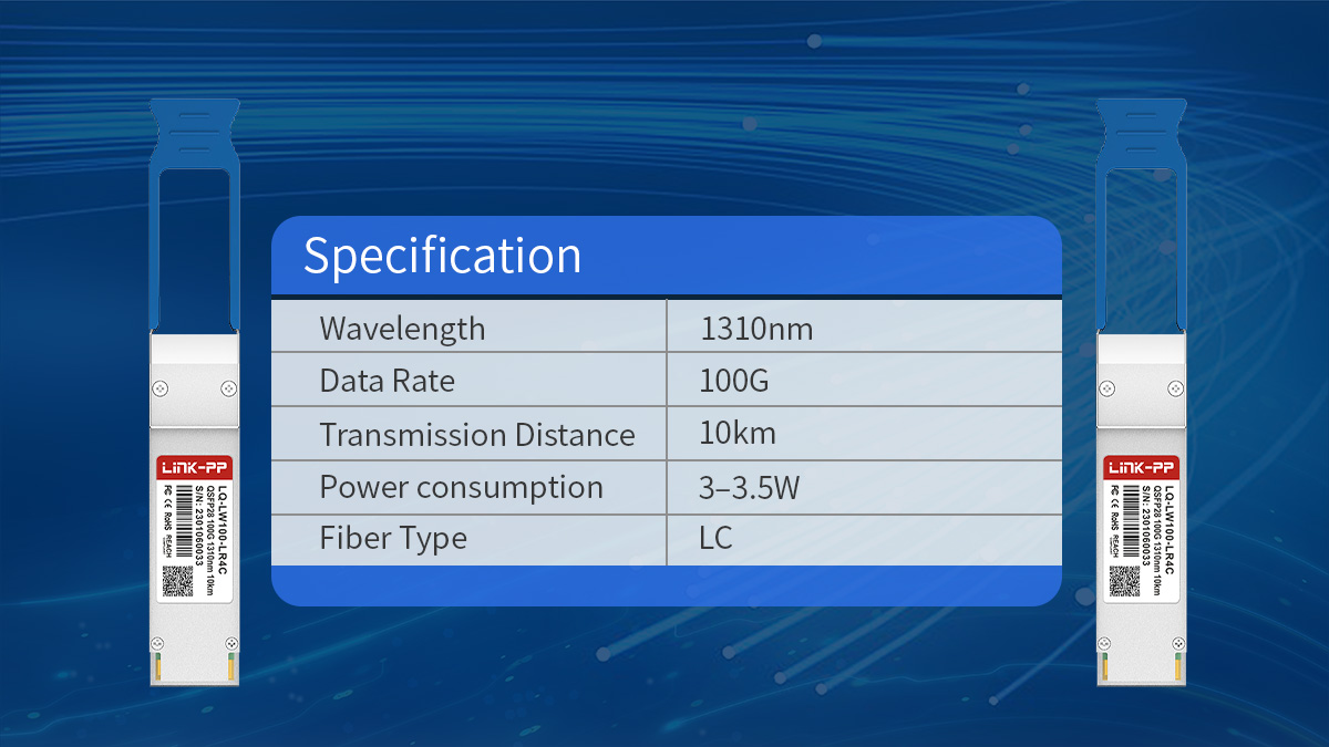
The 100G QSFP28 LR4 follows the IEEE 100GBASE-LR4 standard and is designed for up to 10km transmission over duplex single-mode fiber using LAN-WDM wavelengths. Its specifications define optical performance, power requirements, and interoperability expectations for stable 100GbE long-reach links.
Optical and Electrical Specifications
100G QSFP28 LR4 modules operate as four 25Gbps lanes internally and transmit them over four LAN-WDM wavelengths in the 1310nm region across a duplex SMF link.
| Parameter |
Typical value |
| Form factor |
QSFP28 |
| Data rate |
100Gbps |
| Optical lanes |
4×25Gbps |
| Wavelength scheme |
LAN-WDM (1310nm) |
| Connector |
LC duplex |
| Max reach |
10km |
These parameters define LR4 as a medium-reach single-mode solution positioned between 2km CWDM4 modules and longer-reach ER4 optics. The duplex LC interface allows reuse of standard campus and data center SMF infrastructure.
Most LR4 links rely on host-side FEC (Forward Error Correction) to maintain link margin across longer distances.
Optical Performance and Link Budget
LR4 is engineered for 10km transmission over single-mode fiber with a defined optical budget that accounts for fiber attenuation and connector loss.
| Metric |
Typical range |
| Transmit power (per lane) |
~-4.3 to +4.5dBm |
| Receiver sensitivity |
~-8.6dBm |
| Link budget |
~6–7dB |
| Fiber type |
OS2 SMF |
In real deployments, the effective distance depends on:
- Patch panel count
- Connector quality
- Splice loss
- Safety margin planning
For most campus or DCI environments, LR4 comfortably supports 10km when total link loss remains within the module’s optical budget.
Power Consumption and Thermal Profile
100G QSFP28 LR4 transceiver typically consume more power than short-reach optics due to internal wavelength multiplexing and higher transmit power.
| Attribute |
Typical value |
| Power consumption |
3.5–4.5W |
| Cooling requirement |
Standard front-to-back airflow |
| Form factor cooling |
QSFP28 cage compliant |
Higher power consumption is normal for 10km optics and should be considered in high-density switch deployments where thermal design matters.
Compliance and Standards
LR4 modules are defined by IEEE and MSA specifications to ensure interoperability across vendors.
| Standard |
Scope |
| IEEE 802.3ba |
100GBASE-LR4 definition |
| QSFP28 MSA |
Form factor and interface |
| RoHS |
Environmental compliance |
| DOM/DDM |
Digital monitoring support |
Digital Optical Monitoring (DOM/DDM) allows real-time tracking of:
- Tx/Rx power
- Temperature
- Voltage
- Laser bias
This is critical for long-reach link diagnostics and preventive maintenance.
Compatibility and Interoperability
Most modern switches support QSFP28 LR4 modules, but compatibility depends on coding and firmware alignment.
Key considerations:
- Vendor-coded vs MSA-compatible modules
- Switch FEC configuration
- Optical power interoperability
- Firmware validation
LR4 is generally interoperable across vendors when both sides follow IEEE LR4 specifications, but validation testing is recommended for production networks.
These specifications position the 100G QSFP28 LR4 as a standard solution for 10km duplex SMF 100G links, offering predictable performance for campus backbone, aggregation, and data center interconnect scenarios.
🔷 Cabling and Infrastructure Requirements
The QSFP28 100GBASE-LR4 is designed to operate over duplex single-mode fiber and requires a properly planned optical link budget to reliably achieve its 10km reach. In most enterprise and data center environments, LR4 can be deployed using existing OS2 fiber infrastructure, provided total link loss stays within specification.
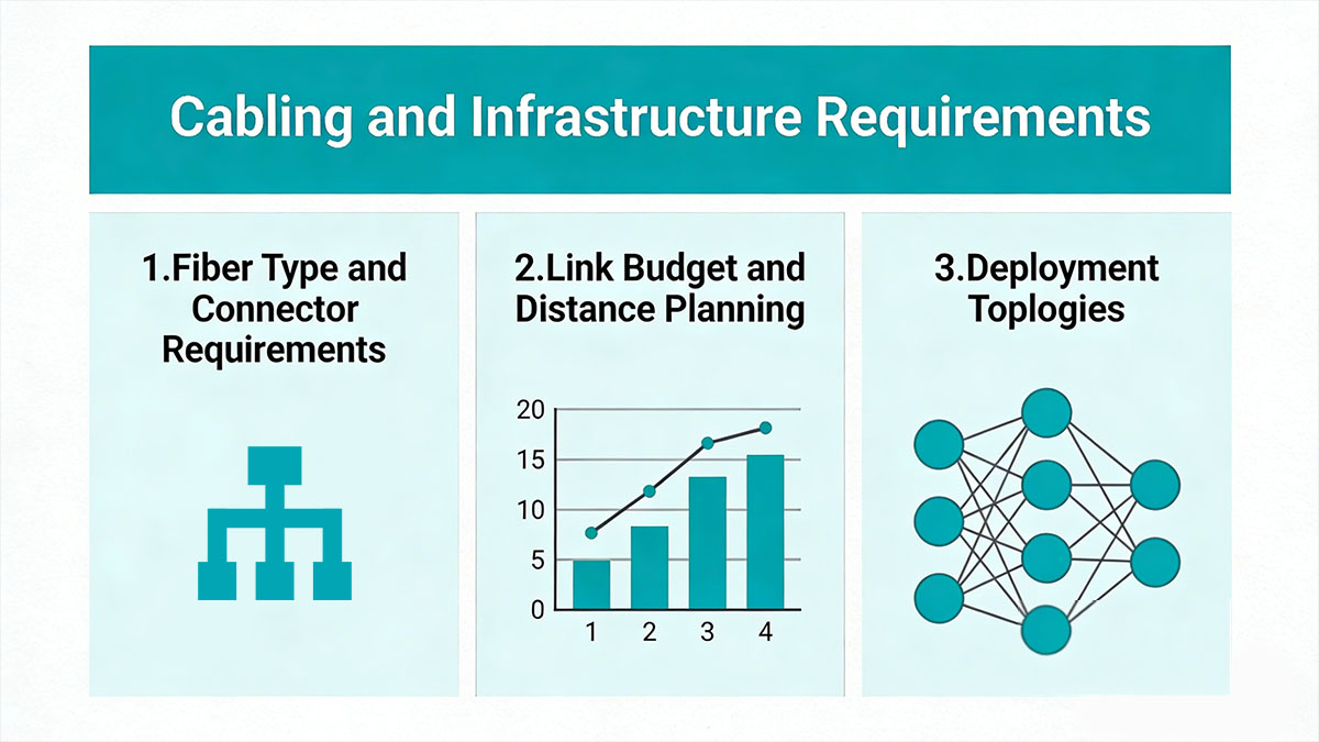
Fiber Type and Connector Requirements
100G QSFP28 LR4 uses duplex LC single-mode fiber and does not require MPO or parallel fiber cabling. This makes it suitable for structured cabling environments where duplex SMF is already installed.
| Cabling element |
Requirement |
| Fiber type |
OS2 single-mode fiber |
| Connector |
LC duplex |
| Fiber count |
2 fibers |
| Max reach |
10km |
Compared with SR4 or PSM4 optics, LR4 simplifies fiber management by using only one fiber pair. This reduces patch panel density requirements and simplifies long-distance routing across buildings or data halls.
To maintain signal quality:
- Use low-loss connectors
- Avoid excessive patching
- Verify polarity
- Clean all LC interfaces before installation
Link Budget and Loss Planning
LR4 supports 10km reach only when total channel loss stays within its optical budget. Typical deployments should maintain sufficient margin for long-term stability.
Most LR4 links operate reliably when total channel loss stays below ~6dB.
| Loss source |
Typical value |
| Fiber attenuation (SMF) |
~0.4dB/km |
| LC connector pair |
0.2–0.5dB |
| Patch panel |
0.3–0.7dB |
| Safety margin |
≥1dB |
When planning a 10km LR4 link:
- Calculate fiber attenuation
- Add connector and patch loss
- Include a safety margin
- Confirm total < module budget
This planning step is critical for campus and metro-edge deployments where multiple patch panels are common.
Patch Panels and Cross-Connect Design
LR4 works well in structured cabling systems with intermediate patch panels, but excessive connections can reduce available margin.
Recommended practices:
- Limit number of cross-connects
- Use low-loss LC adapters
- Avoid unnecessary patch loops
- Test insertion loss after installation
In multi-building environments, keeping total connector count low helps preserve the full 10km capability of LR4 modules.
Deployment Topologies
100G QSFP28 LR4 is typically used in duplex SMF topologies where distances exceed short-reach module limits.
Common infrastructure scenarios:
Campus backbone
- Core-to-aggregation links
- Building-to-building fiber
- Centralized data center uplinks
Data center interconnect (DCI)
- Inter-building connections
- Inter-room links
- Edge data center aggregation
Metro-edge networks
- Access aggregation
- Enterprise metro links
- Carrier edge connections
Because LR4 uses only two fibers, it is often preferred when fiber availability is limited but distance requirements exceed 2km.
Infrastructure Readiness Checklist
Before deploying LR4 modules, verify that the fiber plant meets long-reach requirements.
Checklist:
- OS2 single-mode fiber available
- Total link loss calculated
- LC connectors inspected
- Fiber cleaned and tested
- FEC enabled on switches
- DOM monitoring supported
Completing these checks ensures the LR4 link can operate reliably at full 10km distance without unexpected signal degradation.
A properly designed duplex SMF infrastructure allows 100G QSFP28 LR4 modules to deliver stable long-reach connectivity across campus, data center, and metro-edge networks while minimizing fiber complexity.
🔷 Common Applications of 100G QSFP28 LR4
The 100G QSFP28 LR4 is primarily used for 100GbE links over duplex single-mode fiber at distances up to 10km, making it a practical solution for campus backbones, short-metro interconnects, and multi-building data center environments. It is typically selected when link distance exceeds 2km and MPO-based parallel optics are not preferred.
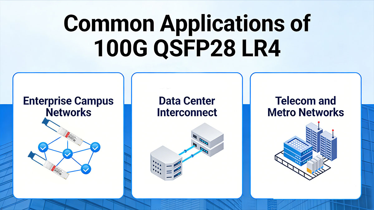
Enterprise Campus Networks
In enterprise campuses, 100G QSFP28 LR4 is most commonly deployed for building-to-building and core uplink connections over existing single-mode fiber infrastructure.
Typical scenarios:
- Building-to-building connectivity across large campuses
- Core-to-aggregation switch uplinks
- Long-distance campus fiber runs between facilities
Why LR4 fits campus environments:
- Supports up to 10km over duplex SMF
- Reuses existing LC-terminated fiber
- Simplifies structured cabling compared with MPO solutions
- Provides stable 100G backbone capacity
In many campus upgrades from 10G or 40G, LR4 becomes the default choice when distances exceed the 2km limit of CWDM4 transceiver.
Data Center Interconnect
LR4 is widely used for inter-building and extended-distance connections between data center spaces within the same campus or metro area.
Common deployments:
- Inter-rack and inter-room connections across large facilities
- Multi-building data center interconnect (DCI)
- Edge data center to central site connectivity
| Scenario |
Typical distance |
Why LR4 is used |
| Inter-room links |
500m–2km |
Margin and stability |
| Building-to-building DCI |
2–10km |
Duplex SMF reuse |
| Edge DC connections |
Up to 10km |
Reliable reach |
LR4 is often preferred over CWDM4 when:
- Total channel loss is higher due to patch panels
- Future distance expansion is possible
- Additional optical margin is required
This makes LR4 a stable choice for scalable 100G DCI architectures.
Telecom and Metro Networks
In telecom and metro-edge environments, 100G QSFP28 LR4 is used for aggregation and access-layer links within the 10km range.
Typical telecom applications:
- Carrier aggregation layer uplinks
- Access network to core connections
- Metro transport links within a city zone
Deployment characteristics:
- Short-metro aggregation rings
- Enterprise-to-POP connections
- Data center to carrier edge links
LR4 is often selected when:
- Distance falls within 10km
- Duplex SMF is already deployed
- ER4 optics would be unnecessary
- Cost and power efficiency are priorities
While not intended for long-haul transport, LR4 provides a practical solution for high-capacity metro-edge links where coherent optics are not required.
Across enterprise, data center, and metro-edge environments, the 100G QSFP28 LR4 is widely used because it delivers predictable 10km reach over standard duplex single-mode fiber while maintaining simple cabling and broad interoperability.
🔷 Advantages and Limitations of QSFP28 LR4
The 100G QSFP28 LR4 is designed for 10km 100GbE transmission over duplex single-mode fiber and is widely used where reliable medium-distance connectivity is required. It balances reach, infrastructure simplicity, and interoperability, but it is not the most cost-efficient choice for short links or distances beyond 10km.
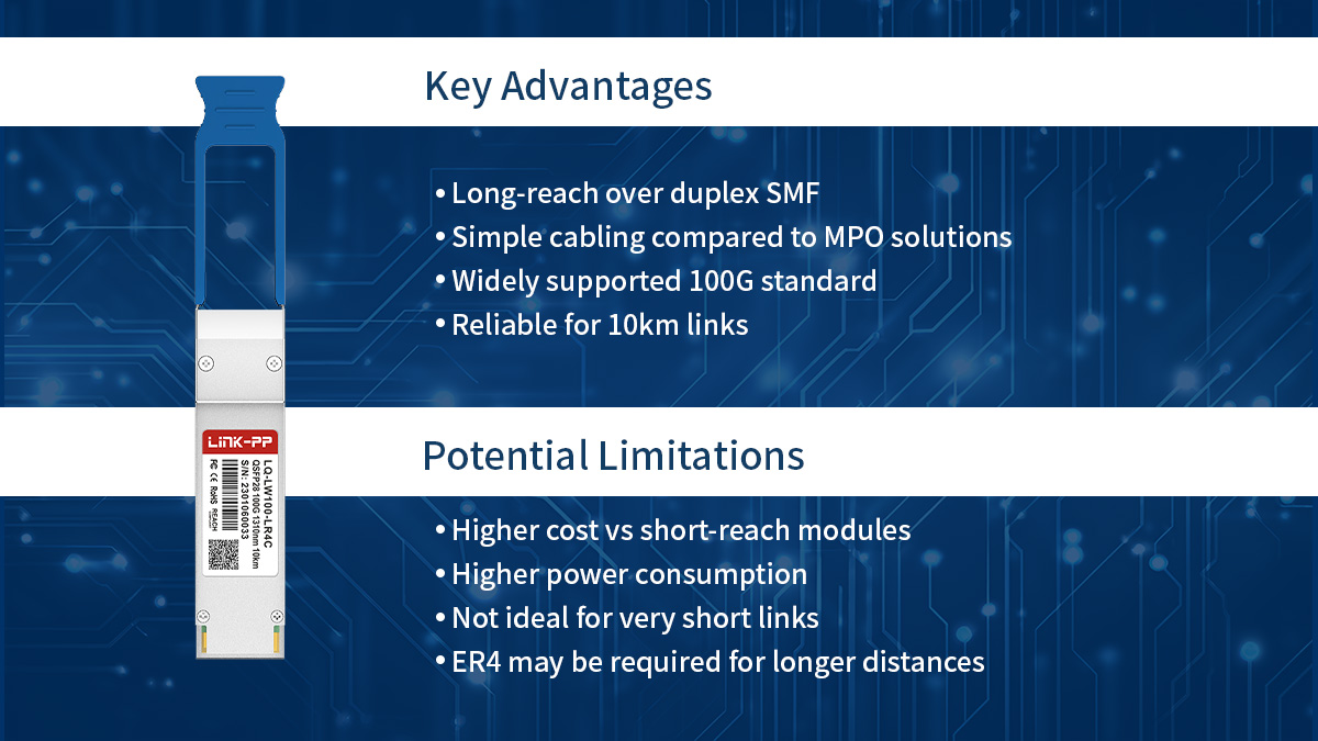
Key Advantages
The primary strength of 100G QSFP28 LR4 lies in its ability to deliver stable 100G links over standard duplex SMF without requiring parallel fiber or complex optical transport systems.
Long-reach over duplex SMF
- Supports up to 10km transmission
- Uses only one fiber pair
- Suitable for campus and DCI links
- Reuses existing single-mode infrastructure
Simpler cabling than MPO-based optics
LR4 avoids the multi-fiber management required by SR4 or PSM4 modules and fits naturally into structured cabling environments built around LC connectors.
| Feature |
LR4 approach |
Parallel optics |
| Fiber count |
2 fibers |
8–12 fibers |
| Connector |
LC duplex |
MPO |
| Cable routing |
Simple |
Higher density |
| Patch management |
Easier |
More complex |
This makes LR4 easier to deploy in buildings, campuses, and multi-room data centers where duplex SMF is already installed.
Widely supported 100G standard
- Defined by IEEE 100GBASE-LR4
- Supported by most enterprise and carrier switches
- Available from multiple vendors
- Interoperable when properly coded
Because LR4 is a mature and widely adopted standard, it is commonly supported across switching platforms and network environments.
Stable performance for 10km links
- Designed optical budget for medium reach
- Reliable with FEC enabled
- Suitable for structured cabling paths
- Predictable link behavior
For many organizations, LR4 provides the most practical way to extend 100G beyond short-reach optics without moving to metro-grade modules.
Potential Limitations
While versatile, LR4 is not always the most economical or technically optimal choice in every deployment scenario.
Higher cost than short-reach modules
- More complex internal optics
- Higher component cost
- Overkill for short distances
For links under 2km, CWDM4 or DR1 modules are often more cost-effective.
Higher power consumption
- Typically around 3.5–4.5W
- Higher than SR4 or DR1
- Impacts high-density switch deployments
This is normal for 10km optics due to the need for higher stable transmit power and wavelength multiplexing.
Not ideal for very short links
Using LR4 for sub-500m links is technically possible but inefficient.
Situations where LR4 may not be optimal:
- In-rack connections
- Same-row switching
- Short data hall links
- High-density leaf-spine fabrics
In these cases, SR4, AOC, or DAC solutions are usually preferred.
Limited to 10km reach
LR4 is designed specifically for the 10km range. When distance requirements exceed this range, ER4 or coherent optics may be necessary.
| Distance need |
Recommended module |
| <100m |
DAC/AOC |
| <500m |
SR4 |
| ≤2km |
CWDM4/DR1 |
| ≤10km |
LR4 |
| >10km |
ER4/ZR |
Choosing the correct module based on distance ensures both cost efficiency and long-term reliability.
Overall, the 100G QSFP28 LR4 offers a strong balance of reach, compatibility, and infrastructure simplicity, making it one of the most widely used 100G single-mode transceivers for campus, aggregation, and data center interconnect networks.
🔷 How to Choose the Right 100G QSFP28 LR4 Module
Selecting a 100G QSFP28 LR4 module requires more than matching distance and connector type. Compatibility with the host device, optical performance margins, and supplier reliability all affect long-term link stability and operational cost. A structured evaluation helps ensure the module performs consistently in production networks.
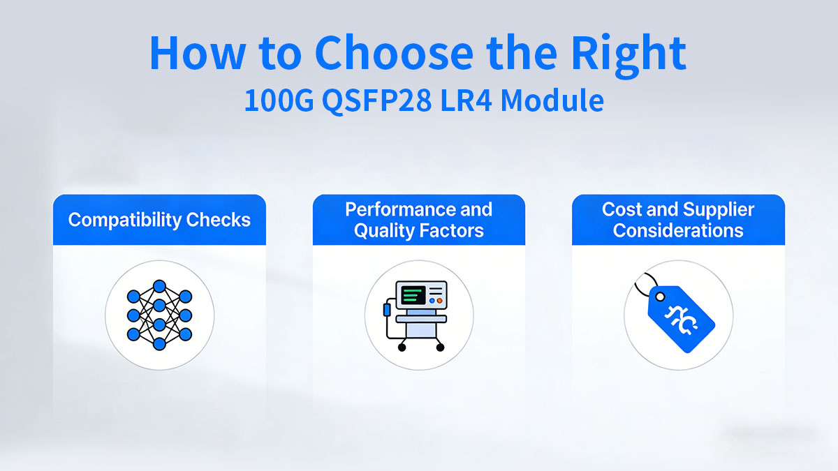
Compatibility Checks
The first step is confirming that the LR4 module will operate correctly with the target switch or router platform.
Key checks:
- Switch vendor coding requirements
- Firmware and OS compatibility
- Forward Error Correction (FEC) support
- DOM/DDM monitoring support
| Compatibility item |
What to verify |
| Vendor coding |
Supported or reprogrammable |
| Switch firmware |
Tested version alignment |
| FEC mode |
RS-FEC or platform default |
| DOM support |
Optical monitoring enabled |
Most modern switches support MSA-compliant LR4 modules, but some vendors enforce coding or firmware validation. Confirming compatibility in advance helps avoid link-up failures or warning messages.
FEC is particularly important for LR4 links because it improves signal integrity over longer distances. Ensure both ends of the link use compatible FEC settings.
Performance and Quality Factors
Optical performance and manufacturing quality determine whether a module can maintain stable 10km operation under real network conditions.
Important factors:
- Transmit power and receiver sensitivity
- Optical budget margin
- Laser stability and calibration
- Burn-in and validation testing
- Long-term reliability metrics
| Performance factor |
Why it matters |
| Tx/Rx power |
Ensures link margin |
| Sensitivity |
Maintains stability at distance |
| Optical budget |
Supports structured cabling loss |
| DOM accuracy |
Enables monitoring |
Modules used in high-availability networks should undergo:
- Optical parameter testing
- Interoperability validation
- Temperature stress testing
- Continuous burn-in
Temperature range selection
Different environments require different module temperature ratings.
- Commercial: 0–70°C (typical data centers)
- Extended: wider tolerance
- Industrial: −40–85°C for harsh sites
Choose industrial-temperature LR4 modules for outdoor cabinets, telecom rooms, or uncontrolled environments.
Cost and Supplier Considerations
Cost evaluation should include not only module price but also reliability, support, and lifecycle value.
Key decision factors:
- OEM vs third-party compatibility modules
- Warranty period
- Technical support availability
- Certification and quality control
- Volume pricing for large deployments
| Factor |
Consideration |
| OEM module |
Highest compatibility assurance |
| Third-party |
Lower cost, requires testing |
| Warranty |
Typical 3–5 years |
| Support |
Firmware and RMA response |
| Certifications |
MSA, RoHS, compliance testing |
Third-party LR4 modules are widely used in enterprise and data center networks when sourced from reputable suppliers that perform:
- Switch compatibility testing
- Optical calibration
- Environmental validation
- Batch consistency checks
For large rollouts, bulk pricing and consistent firmware behavior become especially important. Standardizing on a tested supplier reduces operational risk and simplifies maintenance.
Choosing the right 100G QSFP28 LR4 module ultimately depends on matching switch compatibility, ensuring sufficient optical performance margin, and selecting a supplier with proven testing and support practices.
🔷 Installation and Deployment Tips
Proper installation and validation are essential for stable 100G QSFP28 LR4 operation, especially for links approaching the 10km limit. Most deployment issues are caused by fiber contamination, excessive link loss, or configuration mismatches rather than module defects, so a structured installation process helps ensure reliable performance from day one.
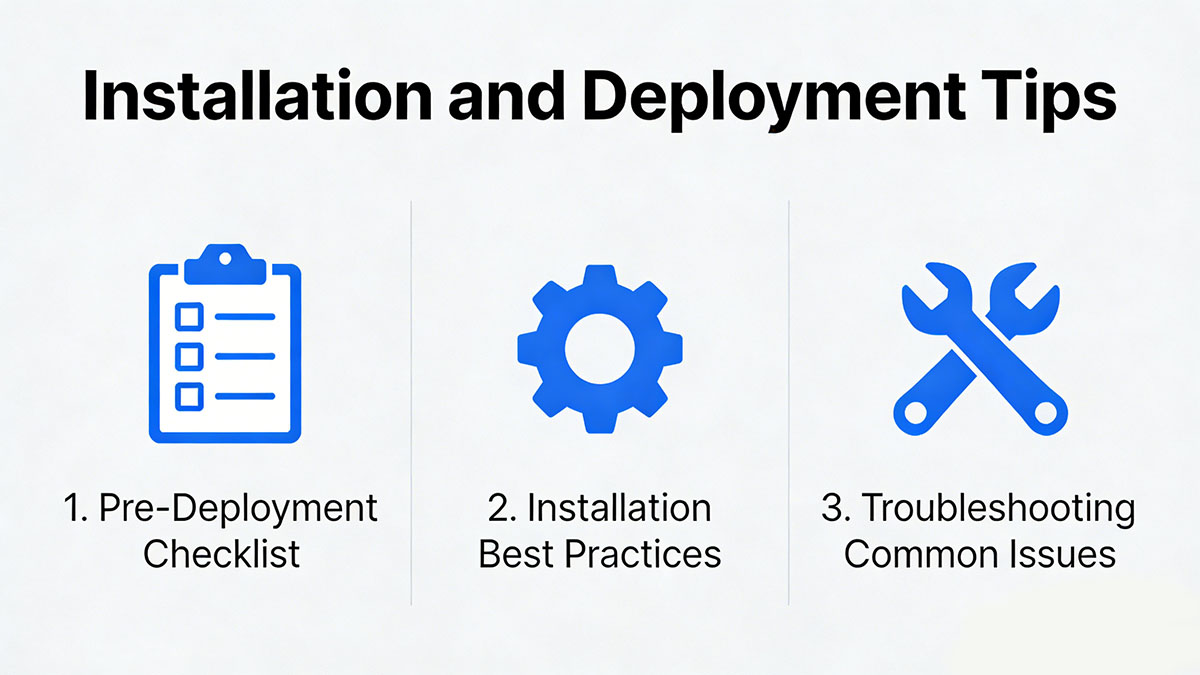
Pre-Deployment Checklist
Before inserting LR4 modules, verify that the fiber plant and switch configuration meet long-reach requirements.
Key pre-deployment steps:
- Inspect and clean all LC connectors
- Confirm total link loss fits within the optical budget
- Verify switch compatibility and coding
- Ensure FEC is supported and configured
- Check fiber polarity and patching path
| Checklist item |
Why it matters |
| Fiber cleaning |
Prevents insertion loss |
| Loss calculation |
Ensures 10km reach |
| Compatibility check |
Avoids link failures |
| FEC readiness |
Improves stability |
Fiber inspection and cleaning
Even small contamination can add measurable loss at 100G. Use a fiber scope and lint-free cleaning tools before connecting modules.
Power budget verification
Calculate total attenuation including fiber length, connectors, and patch panels. Maintain margin below the LR4 link budget to support long-term stability.
Compatibility validation
Confirm the module is recognized by the switch and that firmware supports the selected optics. Perform a test link before full deployment when possible.
Installation Best Practices
Correct handling and monitoring practices help maintain optical performance and prevent avoidable failures.
Recommended practices:
- Insert modules gently and fully latch
- Avoid bending fiber beyond minimum radius
- Use labeled fiber routing
- Monitor DOM values after link-up
- Keep dust caps on unused ports
| Practice |
Benefit |
| Proper insertion |
Prevents port damage |
| Clean connectors |
Reduces loss |
| DOM monitoring |
Detects early issues |
| Controlled routing |
Avoids attenuation |
Monitoring DOM metrics
After installation, check digital optical monitoring (DOM/DDM) values:
- Transmit power
- Receive power
- Temperature
- Voltage
Stable readings within expected ranges confirm that the link budget is adequate.
Avoiding excessive fiber loss
Limit unnecessary patch panels and adapters. Each additional connection increases attenuation and reduces available margin for long-distance LR4 links.
Troubleshooting Common Issues
Most LR4 link problems can be isolated by checking optical power, configuration settings, and compatibility alignment.
Link not up
- Verify fiber polarity
- Confirm both ends use LR4
- Check vendor coding
- Ensure ports are enabled
Power level mismatches
- Inspect and clean connectors
- Measure insertion loss
- Compare DOM Tx/Rx values
- Replace damaged patch cords
| Symptom |
Likely cause |
| No link |
Polarity or compatibility |
| Low Rx power |
Excess loss |
| High Tx alarms |
Faulty module or fiber |
| Flapping link |
Margin or FEC issue |
FEC configuration problems
If FEC settings differ between devices, links may fail to establish or show high error rates. Ensure both ends use compatible FEC modes supported by the platform.
Interoperability issues
- Confirm IEEE LR4 compliance on both ends
- Check firmware versions
- Test with known-good modules
- Validate switch compatibility lists
In multi-vendor environments, interoperability testing before large-scale deployment helps prevent unexpected link behavior.
A careful installation process, proper fiber hygiene, and ongoing DOM monitoring allow 100G QSFP28 LR4 modules to deliver stable 10km performance across campus, data center, and metro-edge networks.
🔷 FAQs About 100G QSFP28 LR4
What distance does 100G QSFP28 LR4 support?
Up to 10km over duplex single-mode fiber when total channel loss stays within the module’s optical budget and FEC is properly configured.
What fiber type is required for QSFP28 LR4?
OS2 single-mode fiber with duplex LC connectors is recommended to achieve full 10km reach and maintain sufficient link margin.
Does 100G QSFP28 LR4 use CWDM or LAN-WDM?
It uses LAN-WDM wavelengths in the 1310nm range, not CWDM. This tighter wavelength spacing enables longer reach compared with CWDM4 modules.
Can QSFP28 LR4 connect to QSFP28 CWDM4?
No. LR4 and CWDM4 use different wavelength plans and optical specifications, so they are not directly interoperable.
Is FEC required for LR4 links?
Most deployments enable FEC on both ends to ensure stable operation at 10km. Exact FEC mode depends on the switch platform.
How much power does a QSFP28 LR4 module consume?
Typical power consumption is around 3.5–4.5W per module, which is higher than short-reach optics due to wavelength multiplexing and longer transmission distance.
Are third-party QSFP28 LR4 modules reliable?
Yes, if they are MSA-compliant and tested for compatibility with the target switch platform. Validation and supplier quality control are key factors.
🔷 Conclusion
The 100G QSFP28 LR4 remains one of the most practical and widely deployed solutions for 100GbE links up to 10km over duplex single-mode fiber. With its LAN-WDM architecture, mature IEEE standardization, and broad switch compatibility, it offers a reliable balance between reach, cabling simplicity, and deployment flexibility across campus backbones, data center interconnects, and metro-edge networks.
For networks that require stable 100G transmission beyond 2km without moving to more complex or higher-cost long-haul optics, LR4 continues to be the standard choice. Selecting the right module involves confirming switch compatibility, validating optical budget margins, and sourcing from a supplier with consistent testing and quality control to ensure long-term link stability.
If you’re planning a 100G deployment or upgrading existing single-mode infrastructure, choosing properly tested and compatible LR4 modules is critical for predictable performance. You can explore tested 100G QSFP28 LR4 solutions and deployment-ready options through the LINK-PP Official Store, where modules are validated for interoperability, reliability, and large-scale network rollouts.