


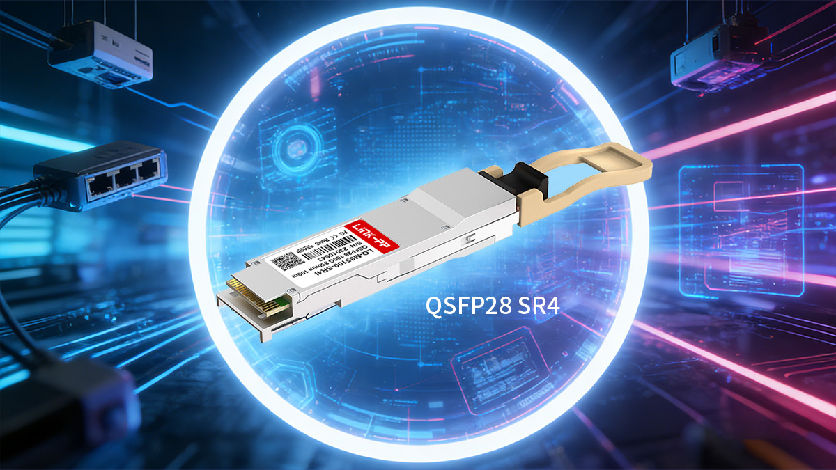
100G QSFP28 SR4 is most suitable for high-density 100G connections within 100m over multimode fiber and is commonly used for spine-leaf links, switch interconnects, and 4×25G breakout scenarios in modern data centers. When multimode MPO infrastructure is already in place or short-reach links dominate the architecture, SR4 is typically the most efficient 100G interface to deploy.
In practical network planning, evaluating QSFP28 SR4 involves more than checking distance and connector type. Platform compatibility, MPO cabling structure, thermal limits, breakout requirements, and overall cost structure all influence whether SR4 is the appropriate interface for a given environment. These factors become especially important in high-port-density switches and large-scale rollouts where consistency and interoperability matter.
This guide provides a structured overview of 100G QSFP28 SR4 specifications, compatibility considerations, cabling design, and deployment scenarios. It is intended for network engineers and infrastructure planners who need a clear technical reference when designing or upgrading short-reach 100G networks based on QSFP28 SR4 optics.
🔀 What Is a 100G QSFP28 SR4 Transceiver?
A 100G QSFP28 SR4 transceiver is a short-reach 100GbE optical module designed for parallel transmission over multimode fiber using an MPO interface, typically supporting distances up to 100m within data centers. It is primarily deployed for high-density switch-to-switch links, leaf-spine architectures, and 4×25G breakout connectivity where short distance and port efficiency are key design factors.
Definition and Core Function
A 100G QSFP28 SR4 module enables 100GbE connectivity by transmitting data over four parallel optical lanes, each operating at 25Gbps, making it optimized for short-distance, high-density environments.
| Parameter | 100G QSFP28 SR4 |
|---|---|
| Ethernet Standard | 100GBASE-SR4 |
| Lane Structure | 4×25Gbps |
| Fiber Type | Multimode (MMF) |
| Connector | MPO/MTP |
| Typical Use | Data center short-reach |
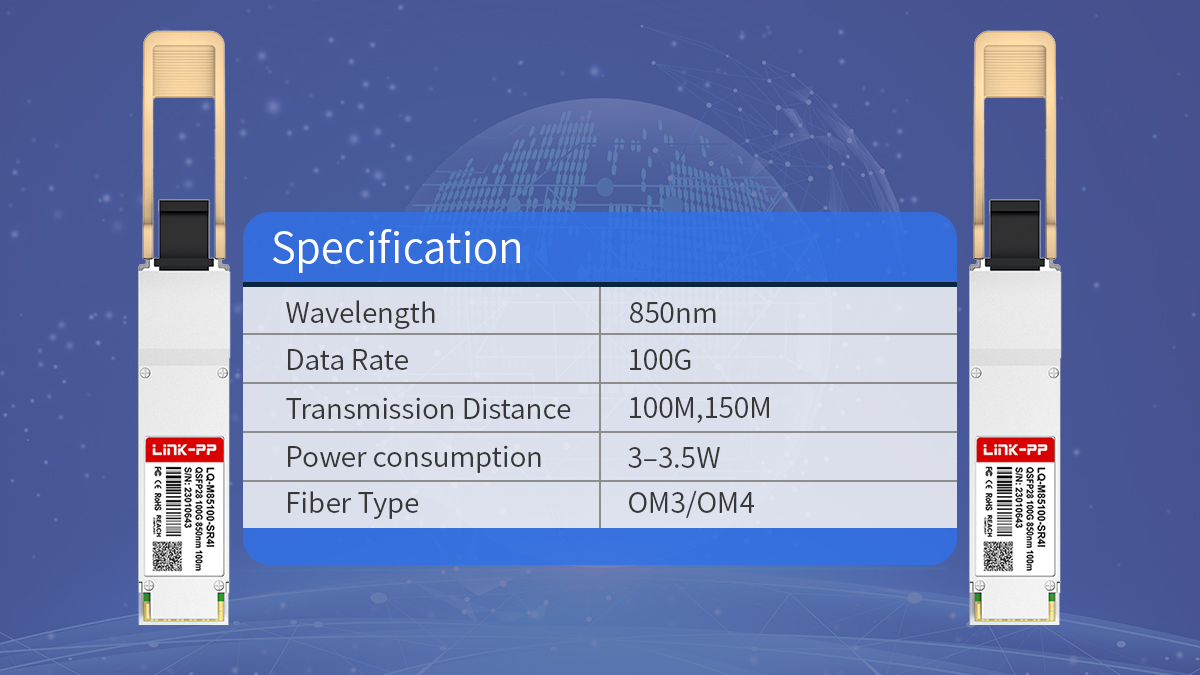
SR4 modules convert electrical signals from the switch into four parallel optical signals at 850nm and transmit them simultaneously over multimode fiber. On the receive side, the four optical lanes are recombined into a single 100G electrical interface. This parallel design allows high bandwidth while maintaining relatively simple optics and predictable power consumption, making SR4 a common choice for short-range 100G interconnects.
How SR4 Works Over Multimode Fiber (MPO/MTP)
100G QSFP28 SR4 operates using parallel optics over an MPO interface, requiring multiple fibers to transmit and receive data simultaneously rather than using wavelength multiplexing.
| Component | Requirement |
|---|---|
| Fiber Count Used | 8 fibers (4 Tx + 4 Rx) |
| Connector Type | MPO-12 (commonly used) |
| Wavelength | 850nm |
| Fiber Type | OM3/OM4 multimode |
Although the physical connector is typically MPO-12, only 8 fibers are actively used for transmission and reception. The remaining fibers are unused in standard SR4 implementations. Because of this structure, SR4 depends on correct MPO polarity, fiber type, and connector gender alignment. Parallel transmission over multimode fiber keeps latency low and simplifies optical design compared with single-mode multiplexing solutions.
Typical Reach and Application Scenarios
100G QSFP28 SR4 is intended for short-distance links within structured data center environments where multimode fiber is already deployed or planned.
| Fiber Type | Maximum Reach |
|---|---|
| OM3 | 70m |
| OM4 | 100m |
| OM5 | 100m+ (depending on design) |
SR4 is commonly used in the following scenarios:
-
Spine-to-leaf connections within the same data hall
-
Top-of-rack to aggregation switch links
-
High-density switch clustering
-
100G to 4×25G breakout connections
-
Short-reach interconnects in AI or compute clusters
Because of its limited distance but high port density, SR4 is most effective when network layouts keep switching layers within relatively short cable runs. In environments requiring longer reach or inter-building connections, single-mode alternatives such as CWDM4 or LR4 are typically evaluated instead.
🔀 Key Specifications of QSFP28 SR4
The most important specifications for a 100G QSFP28 SR4 module are lane structure, connector type, distance limits, power consumption, monitoring capability, and operating range, as these parameters determine compatibility, cabling design, and long-term reliability in a data center environment. Verifying these items early helps avoid interoperability issues and infrastructure mismatches during deployment.
Data Rate and Ethernet Standards
100G QSFP28 SR4 follows the IEEE 802.3bm 100GBASE-SR4 standard and delivers 100Gbps using four parallel 25Gbps lanes, making it compatible with most modern 100G switch ports designed for QSFP28 optics.
| Specification | Value |
|---|---|
| Ethernet Standard | 100GBASE-SR4 |
| Total Data Rate | 100Gbps |
| Lane Count | 4 Tx + 4 Rx |
| Per-Lane Speed | 25Gbps |
| Form Factor | QSFP28 |
Because SR4 uses a standard 4×25Gbps electrical interface, it aligns with common QSFP28 switch ASIC designs. This allows consistent performance across platforms that support 100GBASE-SR4 and simplifies breakout to 25G interfaces when supported by the switch.
Connector Type and Interface
SR4 modules use an MPO interface and rely on parallel fiber transmission, so connector type, polarity, and fiber count directly affect link success.
| Interface Element | Requirement |
|---|---|
| Connector Type | MPO/MTP |
| Physical Format | MPO-12 common |
| Active Fibers | 8 fibers used |
| Polarity Method | Type A/B/C depending on design |
Although the connector is typically MPO-12, only eight fibers are used for data transmission. The remaining fibers are unused but still present physically. Correct polarity and gender matching are essential, especially in structured cabling systems using trunks and patch panels.
Wavelength and Transmission Distance
100G QSFP28 SR4 operates at 850nm over multimode fiber, with distance determined primarily by fiber grade and total link loss.
| Fiber Type | Maximum Reach |
|---|---|
| OM3 | 70m |
| OM4 | 100m |
| OM5 | ~100m+ (design dependent) |
Distance limits assume typical insertion loss and standard patching. Additional patch panels or poor connector quality can reduce achievable reach. In environments approaching distance limits, OM4 is generally preferred over OM3 to maintain margin.
Power Consumption and Thermal Design
SR4 modules typically consume less power than longer-reach single-mode 100G optics, making them suitable for high-density switch environments.
| Parameter | Typical Value |
|---|---|
| Power Consumption | ~3–3.5W |
| Cooling Requirement | Standard airflow |
| Density Suitability | High-port switches |
Lower power consumption helps maintain thermal stability in switches with many 100G ports. This becomes particularly important in spine switches or modular chassis with high optical density, where cumulative heat output can affect system performance.
Digital Diagnostics Monitoring (DDM/DOM)
Most 100G QSFP28 SR4 modules support digital diagnostics monitoring, allowing real-time visibility into optical and module performance.
| Monitoring Item | Supported |
|---|---|
| Temperature | Yes |
| Voltage | Yes |
| Tx/Rx Optical Power | Yes |
| Module Alarms | Yes |
DDM support enables proactive maintenance by allowing operators to detect signal degradation, overheating, or power anomalies before link failures occur. Integration with switch monitoring systems provides continuous visibility into optical link health.
Operating Temperature and Reliability
SR4 modules are typically designed for controlled data center environments, but operating temperature range and reliability ratings still influence long-term stability.
| Parameter | Typical Range |
|---|---|
| Operating Temperature | 0°C to 70°C |
| Storage Temperature | −40°C to 85°C |
| Environment | Data center indoor |
| Reliability Metric | High MTBF expected |
Most deployments use commercial temperature-range modules suitable for climate-controlled facilities. In environments with higher ambient temperature variation, verifying thermal tolerance and airflow design helps maintain stable performance over time.
🔀 Compatibility Considerations of QSFP28 SR4
QSFP28 SR4 modules are standardized under 100GBASE-SR4, but practical compatibility depends on switch platform support, EEPROM coding, firmware behavior, and cross-vendor interoperability. Verifying these factors ensures stable links, accurate monitoring, and predictable behavior across large-scale deployments.
Switch and Router Platform Support
Most modern 100G switches support QSFP28 SR4, but platform-level validation is still required because port firmware, optics policies, and breakout behavior can vary.
| Platform Type | Compatibility Notes |
|---|---|
| Data center switches | Broad SR4 support |
| Modular chassis | Check line card support |
| Older 100G platforms | Firmware validation required |
| 25G breakout ports | Confirm breakout capability |
Before deployment, confirm:
-
The port supports 100GBASE-SR4 mode
-
Breakout to 4×25G is supported if required
-
The switch OS recognizes DOM/DDM values
-
Optics policy does not restrict third-party modules
Platform documentation and compatibility matrices provide the most reliable verification.
Vendor-Coded vs Multi-Compatible Modules
QSFP28 modules contain EEPROM coding that identifies the module to the host switch. Proper coding ensures that the switch accepts the module and enables monitoring features.
| Coding Type | Behavior |
|---|---|
| Vendor-coded | Recognized as native optics |
| Multi-compatible | Works across platforms |
| Generic coding | May limit features |
| Locked coding | Restricted to one vendor |
Vendor-coded modules are programmed for a specific platform, while multi-compatible modules are designed to work across multiple switch brands. The key requirement is that coding matches the switch expectations so the port initializes correctly and monitoring data remains accessible.
Cross-Vendor Interoperability
SR4 modules from different manufacturers can typically interoperate if they follow IEEE and MSA standards, but validation is still recommended for large deployments.
| Interoperability Factor | Impact |
|---|---|
| Standard compliance | Enables cross-linking |
| Optical power levels | Must align within budget |
| Connector quality | Affects signal integrity |
| Firmware behavior | May affect alarms |
In mixed environments:
-
Ensure both ends meet 100GBASE-SR4 specs
-
Validate optical power within supported range
-
Test representative links before scaling
-
Confirm no vendor-specific alarms are triggered
Parallel multimode optics are generally tolerant of mixed vendors, but structured testing avoids unexpected link behavior.
Software and Firmware Factors
Switch firmware and operating system versions influence how SR4 modules are recognized and managed, particularly in environments with monitoring or security policies.
| Firmware Aspect | Consideration |
|---|---|
| Optics recognition | Requires supported coding |
| DOM visibility | Depends on OS support |
| Alarm thresholds | Platform-defined |
| Port mode configuration | Must match SR4 |
When planning deployment:
-
Verify the switch OS supports SR4 modules
-
Check if firmware enforces optics validation
-
Confirm DOM data is readable
-
Ensure correct port mode (100G or breakout)
Firmware updates can sometimes change optics behavior, so validation after major updates helps maintain stable operation.
🔀 Pricing and Cost Structure Factors About 100G SR4
The overall cost of deploying 100G SR4 links is determined by module type, deployment scale, cabling infrastructure, and lifecycle planning rather than module price alone. In short-reach data center environments where multimode MPO fiber is already in place, SR4 often provides a predictable and efficient cost structure compared with longer-reach 100G optics.
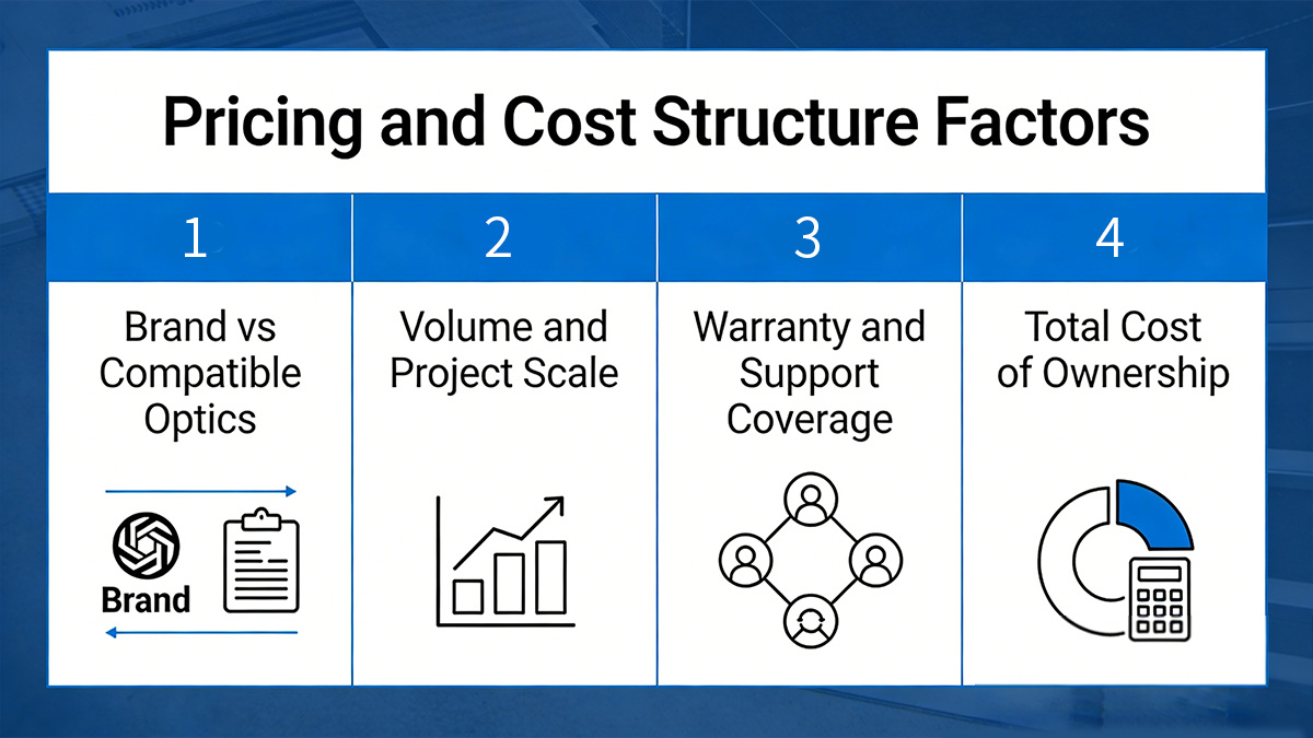
Brand vs Compatible Optics
Standards-compliant compatible SR4 modules and original-brand optics follow the same 100GBASE-SR4 specifications, but their cost structure differs mainly due to coding, certification processes, and support models rather than transmission performance.
When evaluating module type, the main decision points include:
-
Switch policy requirements
Some platforms require vendor-coded optics or specific EEPROM profiles to enable full functionality and monitoring. -
Operational consistency
Large environments often standardize on one module type to simplify inventory and validation. -
Support expectations
Warranty terms, replacement procedures, and technical assistance can influence long-term operating cost. -
Interoperability planning
Multi-vendor environments may prioritize modules validated across multiple switch platforms.
In many data center scenarios where IEEE and MSA compliance is sufficient, compatible coded modules provide similar short-reach performance while allowing more flexibility in large-scale rollouts.
Volume and Project Scale
Per-link cost decreases as deployment scale increases because validation, logistics, and spare management can be standardized across the project.
Key factors that influence cost at scale include:
-
Standardization of module type
Using one consistent SR4 specification across racks reduces compatibility testing and simplifies spares. -
Inventory strategy
Maintaining a defined spare ratio prevents urgent replacements from disrupting operations. -
Batch validation
Testing representative links before full rollout helps avoid repeated troubleshooting across hundreds of connections. -
Deployment timing
Coordinated installation during switch upgrades or new builds reduces operational overhead.
For small deployments, flexibility and immediate compatibility may matter more than cost optimization. For large-scale environments, consistency and lifecycle planning often have a greater impact on total cost.
Warranty and Support Coverage
Warranty terms and support responsiveness affect operational cost, particularly in high-density switch environments where many optics are deployed simultaneously.
When evaluating support coverage, consider:
-
Warranty duration
Longer coverage periods help align with switch lifecycle planning. -
Replacement process
Clear RMA procedures reduce downtime when modules fail. -
Advance replacement options
Faster replacement reduces risk in critical links. -
Technical support access
Availability of troubleshooting assistance helps resolve compatibility or link issues quickly.
In environments with hundreds of SR4 links, predictable replacement and support processes can reduce operational disruption more than small differences in module price.
Total Cost of Ownership
The total cost of ownership for 100G QSFP28 SR4 includes optics, fiber infrastructure, power consumption, and long-term maintenance.
SR4 tends to provide an efficient cost structure when the following conditions apply:
-
Multimode MPO infrastructure is already deployed
-
Link distances remain within 100m
-
High port density is required
-
Breakout to 25G interfaces is planned
However, if links approach distance limits, require inter-building connectivity, or depend on single-mode fiber, other 100G interfaces may become more suitable despite higher module cost. Evaluating infrastructure alignment and future expansion plans helps determine whether SR4 remains the most practical choice over the network lifecycle.
🔀 QSFP28 SR4 Module's Cabling and Infrastructure Planning
100G QSFP28 SR4 relies on parallel multimode fiber and MPO connectivity, so cabling design directly determines whether links operate reliably and reach expected distances. Proper planning around fiber type, MPO polarity, and breakout structure ensures that SR4 links can be deployed consistently across racks and switch layers without repeated reconfiguration.
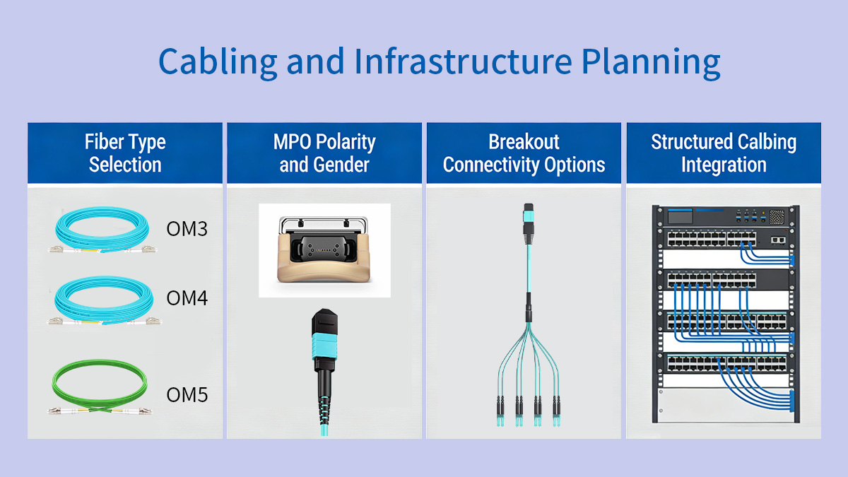
Fiber Type Selection
For most data center environments, OM4 multimode fiber provides the most reliable distance margin for 100G QSFP28 SR4, while OM3 can be used for shorter runs within the same rack row.
| Fiber Type | Typical SR4 Reach | Deployment Use |
|---|---|---|
| OM3 | up to 70m | Same-row links |
| OM4 | up to 100m | Standard choice |
| OM5 | ~100m+ | Niche designs |
OM3 remains suitable for very short interconnects, but OM4 is generally preferred for new installations because it provides additional margin for patch panels, connectors, and future reconfiguration. In environments where cable paths may expand over time, using OM4 helps avoid reaching distance limits.
MPO Polarity and Gender
Correct MPO polarity and connector gender are essential for SR4 links because the module transmits and receives over separate fiber lanes. Misalignment will prevent links from establishing.
When planning polarity:
-
Determine whether the structured cabling uses Type A, B, or C polarity
-
Confirm male vs female MPO connectors at each endpoint
-
Verify trunk cable polarity through patch panels
-
Keep polarity consistent across rows and zones
SR4 modules typically use an MPO interface with eight active fibers. Even though MPO-12 connectors are common, only eight fibers carry traffic, so maintaining consistent polarity mapping ensures transmit lanes align with receive lanes across the link.
Breakout Connectivity Options
100G QSFP28 SR4 supports breakout to four 25G links, making it useful in environments where switches connect to multiple 25G server-facing ports.
Breakout is appropriate when:
-
The switch supports 4×25G breakout mode
-
MPO-to-4×LC breakout cables are used
-
Each 25G link connects to an SFP28 port
-
Switch configuration matches breakout mode
Breakout design considerations include:
-
Confirming port mode configuration in the switch OS
-
Matching cable type (MPO to 4×LC)
-
Maintaining consistent labeling across racks
-
Planning patch panel layout to avoid cross-connect errors
Because breakout relies on lane-level mapping, structured documentation and consistent cabling layouts help prevent confusion during maintenance or expansion.
Structured Cabling Integration
SR4 works best in structured cabling environments where MPO trunks and patch panels are already standardized across rows or zones.
Key planning considerations:
-
Use trunk cables to connect rows or switch zones
-
Minimize excessive patching to preserve link budget
-
Label MPO trunks and patch panels clearly
-
Keep cable paths within SR4 distance limits
In high-density data halls, structured MPO cabling allows SR4 links to be deployed quickly without redesigning fiber paths for each new switch. Aligning SR4 deployment with the overall cabling architecture helps maintain consistency and simplifies future upgrades.
🔀 Typical Deployment Scenarios of 100G SR4
100G QSFP28 SR4 is most effective in short-reach, high-density environments where multimode MPO fiber is already part of the cabling infrastructure and link distances remain within 100m. It is commonly used inside a single data hall for switch interconnects, aggregation layers, and breakout architectures that prioritize port density and predictable deployment.
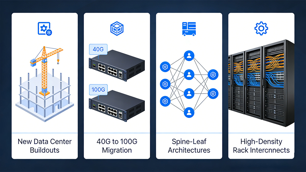
New Data Center Buildouts
In newly built data centers, SR4 is often selected for short-distance backbone links because it aligns well with structured MPO cabling and high-port-density switch designs.
Typical use conditions include:
-
Spine and leaf switches located within the same row or hall
-
Structured MPO trunk cabling between racks
-
High port density requirements on spine switches
-
Consistent link lengths under 100m
SR4 allows planners to standardize short-reach 100G links across the facility, simplifying installation and reducing variability in optical behavior. When OM4 fiber and MPO patching are included in the initial design, SR4 can be deployed at scale with minimal additional infrastructure planning.
40G to 100G Migration
SR4 is commonly used when upgrading from 40G parallel multimode links to 100G because existing MPO cabling can often be reused.
Migration scenarios typically involve:
-
Replacing QSFP+ SR4 with QSFP28 SR4
-
Maintaining existing MPO trunk cables
-
Increasing port bandwidth without changing fiber paths
-
Reusing patch panels and cable routes
Because both 40G SR4 and 100G SR4 rely on parallel multimode transmission, many data centers can transition to 100G while preserving the underlying fiber plant. This reduces disruption and allows upgrades to occur incrementally as switches are replaced.
Spine-Leaf Architectures
In spine-leaf topologies, SR4 is frequently used for leaf-to-spine links when switches are located within short cable distance of each other.
SR4 fits best when:
-
Leaf and spine switches are in the same data hall
-
Cable runs remain within multimode distance limits
-
High port density is required on spine switches
-
Low-latency short links are prioritized
Because these links are typically numerous and short, SR4 provides a consistent and scalable way to interconnect switches without requiring single-mode fiber for every connection. This helps maintain uniform cabling and predictable link behavior across the fabric.
High-Density Rack Interconnects
SR4 is also used for high-density interconnects within or between adjacent racks, especially in compute clusters and storage networks.
Common scenarios include:
-
Switch clustering within the same row
-
Aggregating multiple top-of-rack switches
-
Connecting GPU or compute clusters
-
High-bandwidth east-west traffic patterns
In these environments, link distances are short but bandwidth requirements are high. SR4 allows multiple 100G connections to be deployed within limited rack space while maintaining manageable power consumption and thermal output.
🔀 How to Choose a Reliable QSFP28 SR4 Provider
A reliable 100G QSFP28 SR4 module provider should demonstrate consistent standards compliance, validated compatibility, stable supply, and responsive technical support. Because SR4 is often deployed at scale across many ports, provider consistency directly affects interoperability, maintenance efficiency, and long-term network stability.
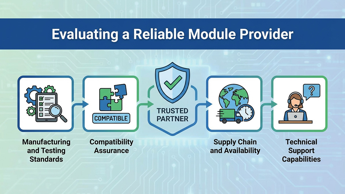
Manufacturing and Testing Standards
Modules that follow IEEE 802.3bm and relevant MSA specifications are more likely to interoperate across platforms and maintain stable optical performance over time.
When evaluating manufacturing and testing practices, look for:
-
Compliance with 100GBASE-SR4 optical and electrical standards
-
Optical power and sensitivity testing for each unit
-
Temperature and stability testing under load
-
Burn-in procedures to reduce early failure rates
-
Clear documentation of test methodology
Consistent production testing helps ensure that modules perform predictably across large deployments where even small variations can affect link stability.
Compatibility Assurance
Compatibility validation is essential because switch platforms may enforce optics recognition rules or require specific EEPROM coding to enable full functionality.
Key compatibility indicators include:
-
Platform-specific coding support
-
Multi-vendor compatibility validation
-
DOM/DDM functionality confirmation
-
Port initialization testing
-
Interoperability test reports
In multi-vendor environments, modules that have been tested across common switch platforms help reduce troubleshooting time and simplify rollout planning.
Supply Chain and Availability
For environments deploying dozens or hundreds of SR4 links, supply consistency matters as much as technical performance.
Important supply considerations:
-
Stable inventory levels for ongoing expansion
-
Predictable lead times for large orders
-
Consistent hardware revisions across batches
-
Clear product lifecycle management
-
Regional logistics support
Using modules with consistent revision control helps avoid mixing hardware variants that could behave differently in large networks.
Technical Support Capabilities
Responsive technical support helps resolve compatibility questions, link issues, and deployment challenges more efficiently.
Support capabilities to consider:
-
Pre-deployment compatibility guidance
-
Assistance with link troubleshooting
-
Documentation for configuration and testing
-
Replacement and RMA coordination
-
Long-term product support
In high-density 100G environments, having access to knowledgeable support can significantly reduce the time required to diagnose link issues or validate interoperability across platforms.
🔀 100G QSFP28 SR4 vs Other 100G Modules
100G QSFP28 SR4 is optimized for short-distance multimode links inside a data center, while other 100G modules such as CWDM4, PSM4, and LR4 are designed for longer reach or different fiber types. Choosing the correct interface depends primarily on distance, fiber infrastructure, and port density requirements.
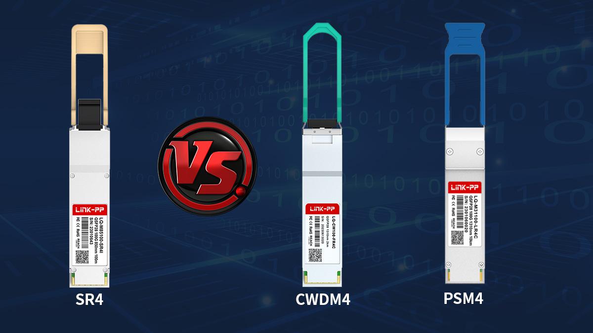
SR4 vs CWDM4
SR4 is typically preferred for short multimode links within 100m, while CWDM4 is used for longer connections over single-mode fiber up to several kilometers.
| Factor | QSFP28 SR4 | QSFP28 CWDM4 |
|---|---|---|
| Fiber Type | Multimode | Single-mode |
| Typical Reach | ≤100m | ~2km |
| Connector | MPO | Duplex LC |
| Cabling Cost | Lower (MMF) | Higher (SMF) |
| Use Case | In-rack / row | Inter-row / campus |
SR4 is generally used when switches are located within the same data hall and multimode MPO infrastructure is available. CWDM4 becomes more appropriate when distances exceed SR4 limits or when single-mode fiber is already deployed across rows or buildings.
SR4 vs PSM4
SR4 and PSM4 both use parallel optics, but they differ in fiber type and typical deployment environment.
| Factor | QSFP28 SR4 | QSFP28 PSM4 |
|---|---|---|
| Fiber Type | Multimode | Single-mode |
| Reach | ≤100m | up to 2km |
| Connector | MPO | MPO |
| Infrastructure | MMF | SMF |
| Use Case | Data hall | Campus/metro short links |
SR4 is usually selected when multimode fiber is present and distances are short. PSM4 is more suitable when longer reach is needed but parallel MPO cabling is still preferred over duplex LC solutions.
When SR4 Is the Most Efficient Choice
SR4 is typically the most efficient 100G interface when link distances are short and high port density is required within a structured multimode cabling environment.
SR4 fits best under these conditions:
-
Link distances remain under 100m
-
Multimode MPO cabling is already installed
-
High-density switch ports are needed
-
Breakout to 4×25G is required
-
Most links stay within a single data hall
If distances extend beyond SR4 limits, if single-mode fiber is standard across the facility, or if inter-building connectivity is required, CWDM4, LR4, or other single-mode interfaces are generally more suitable.
🔀 Installation and Deployment Best Practices
Proper handling, deployment, and validation of 100G QSFP28 SR4 links are essential to ensure consistent performance, reliable connectivity, and minimal troubleshooting in high-density data center environments. SR4 relies on parallel multimode MPO fiber, so careful attention to connector handling, polarity, and pre-deployment testing is critical.
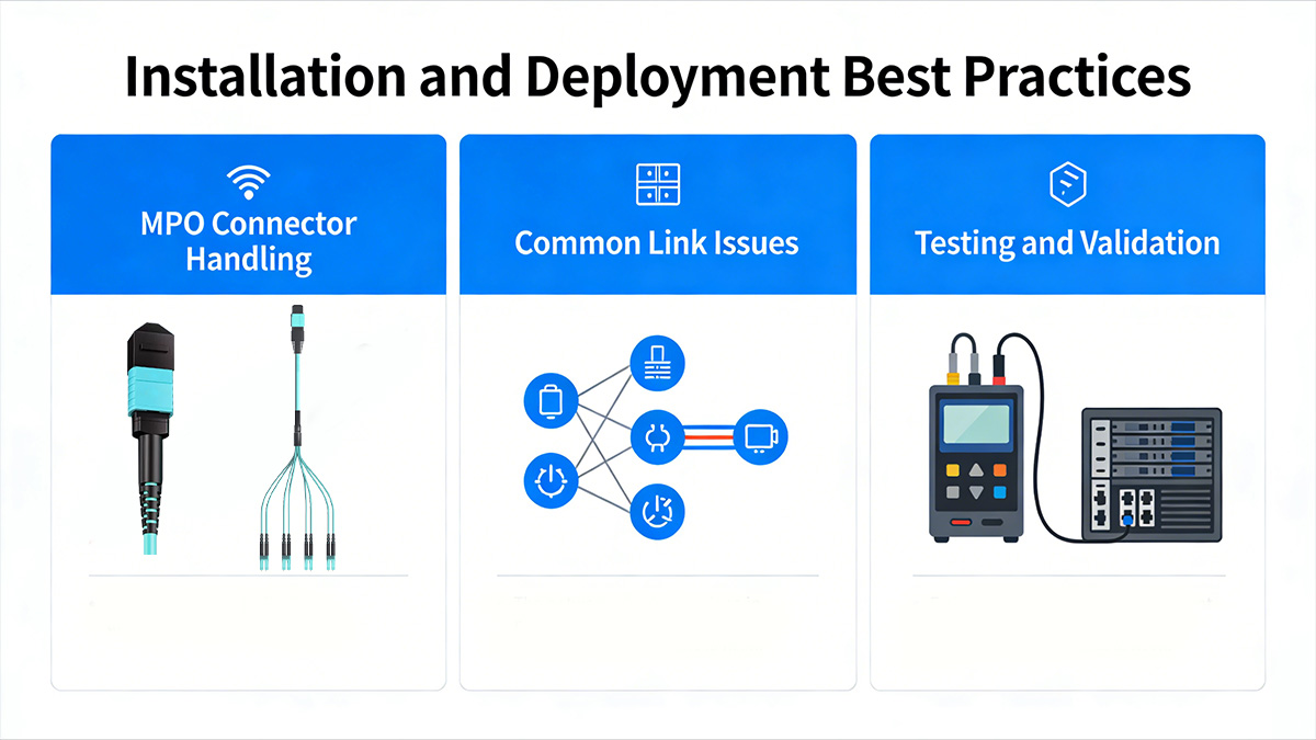
MPO Connector Handling
Correct MPO handling prevents signal degradation and ensures that SR4 modules operate within specifications. Mishandling can cause insertion loss, contamination, or permanent connector damage.
Key practices include:
-
Cleaning Procedures: Use approved fiber cleaning tools or lint-free wipes for MPO ferrules before installation.
-
Inspection Tools: Employ fiber inspection scopes to verify end-face cleanliness and detect scratches or debris.
-
Avoiding Insertion Loss: Ensure proper alignment when mating connectors, avoid excessive force, and verify that connectors are fully seated without gaps.
Maintaining clean and properly handled MPO connectors significantly reduces the risk of degraded optical performance and link failures.
Common Link Issues
Several factors can cause SR4 links to fail or perform suboptimally. Recognizing these issues early helps prevent deployment delays.
Typical link issues include:
-
Polarity Mismatches: Incorrect MPO polarity mapping can prevent transmit and receive lanes from aligning.
-
Dirty Connectors: Contaminated fiber faces increase insertion loss and reduce optical power.
-
Incorrect Fiber Types: Using OM3 where OM4 is required, or vice versa, can limit reach or signal margin.
Addressing these issues before full deployment ensures links operate reliably and reduces maintenance overhead.
Testing and Validation
Testing SR4 links before production deployment verifies that modules and fiber paths meet performance requirements.
Key validation steps include:
-
Optical Power Testing: Measure Tx and Rx optical power to confirm it is within the module’s specified range.
-
Loopback Validation: Use loopback cables or test ports to verify each link’s end-to-end connectivity.
-
Pre-Deployment Checks: Confirm module coding, port compatibility, MPO polarity, and fiber type alignment.
Systematic testing and validation help detect potential problems early, allowing corrections before scaling deployment across racks or data halls.
🔀 FAQs About 100G QSFP28 SR4
Q1: What is the maximum transmission distance of 100G QSFP28 SR4?
A: SR4 supports up to 100 meters on OM4 multimode fiber and approximately 70 meters on OM3. Distance depends on cable quality, patch panels, and insertion loss.
Q2: Can SR4 modules be used for 4×25G breakout?
A: Yes, SR4 supports 4×25G breakout if the switch port allows breakout mode and MPO-to-4×LC breakout cables are used.
Q3: What type of connector interface does SR4 use?
A: SR4 uses an MPO interface, usually MPO-12, with 8 active fibers (4 transmit + 4 receive). Correct polarity and gender alignment are required for proper operation.
Q4: Why is the SR4 link not coming up after installation?
A: The most common causes are polarity mismatches, dirty connectors, or incorrect fiber type. Inspect and clean connectors, verify fiber type and MPO polarity, and confirm switch port configuration.
Q5: How can I monitor the optical performance of SR4 modules?
A: Enable DOM/DDM monitoring to track Tx/Rx optical power, voltage, and temperature. Abnormal readings may indicate contamination, fiber issues, or distance exceeding specifications.
Q6: Can SR4 modules from different vendors interoperate?
A: Yes, provided they follow IEEE 802.3bm and MSA standards. Always validate on the target switch platform to avoid issues with coding recognition, DOM reporting, or firmware restrictions.
Q7: How can I optimize SR4 performance in a high-density data center?
A: Keep cable runs within OM3/OM4 distance limits, maintain clean MPO connectors, minimize patch panels/adapters, and use OM4 fiber in high-density areas for better signal margin.
Q8: How should I plan for future network upgrades with SR4?
A: Document cabling layouts, labeling, and patch panel assignments to allow easy breakout, switch replacement, or fiber migration without affecting existing links.
🔀 Conclusion
100G QSFP28 SR4 modules provide a reliable, high-density, and short-reach 100G solution for modern data center environments. They excel in structured multimode MPO cabling, support breakout to 4×25G, and offer predictable optical performance when properly installed and validated. By carefully evaluating module specifications, cabling infrastructure, and deployment practices, SR4 can deliver efficient, scalable, and low-maintenance 100G connectivity.
For engineers and network planners looking to ensure consistent 100G performance with SR4, explore the full range of certified modules and accessories at the LINK-PP Official Store