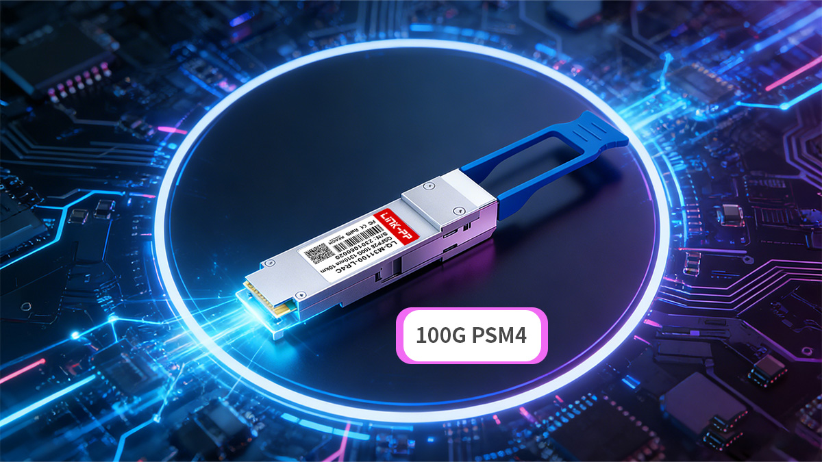
100G QSFP28 PSM4 is a cost-efficient 100Gbps optical transceiver designed for short-reach data center links where parallel single-mode fiber infrastructure is available. It is most commonly used for spine-leaf connections, switch-to-switch links, and high-density east-west traffic inside hyperscale and enterprise data centers up to 2km.
As 100GbE deployments scale, network architects increasingly need a solution that balances port cost, fiber availability, and deployment simplicity. While wavelength-multiplexed optics such as CWDM4 and DR4 are widely used for duplex fiber environments, many modern data centers — especially those built for cloud, AI, or HPC workloads — already deploy parallel single-mode cabling. In these environments, 100G PSM4 offers a straightforward and scalable way to deliver high-bandwidth connectivity without the added complexity of wavelength multiplexing.
From an architectural standpoint, 100G PSM4 transmits four parallel 25Gbps lanes over single-mode fiber using an MPO-12 interface. This parallel design allows operators to reuse existing MPO-based fiber trunks, maintain consistent cabling structures across 40G and 100G layers, and reduce per-port optical costs in large-scale deployments. As a result, PSM4 has become a practical choice for intra-data-center interconnects where link distances remain within 2km and high port density is required.
This article focuses on the real-world role of 100G PSM4 in modern networks. Instead of only explaining specifications, it examines:
-
Where 100G PSM4 fits best
-
When it should be chosen over other 100G interfaces
-
How it is deployed in actual data center environments
-
What practical considerations affect design decisions
By understanding both the application scenarios and deployment strategies, network designers can determine whether 100G PSM4 is the right solution for their infrastructure and scaling roadmap.
🔰 What Is 100G PSM4?
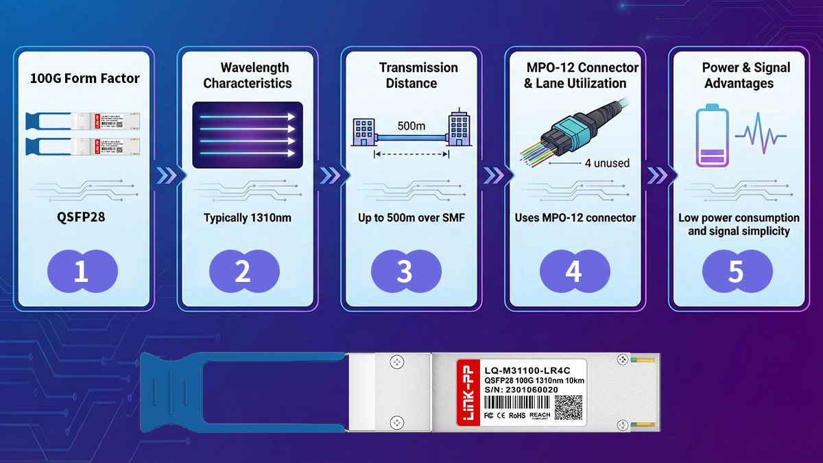
100G PSM4 is a parallel single-mode optical interface that delivers 100Gbps using four independent 25Gbps lanes over single-mode fiber, typically for short-reach data center links up to 2km. It is primarily used in high-density intra-data-center environments where MPO-based parallel fiber infrastructure is already deployed and cost per 100G port must be controlled.
Unlike wavelength-multiplexed 100G optics that transmit multiple wavelengths over duplex fiber, PSM4 uses a parallel architecture. Each optical lane carries 25Gbps, and four transmit plus four receive lanes operate simultaneously to form a 100Gbps link. This approach simplifies optical design and is well suited to large-scale data center fabrics where short-reach connectivity dominates.
Architecture and Transmission Method
100G PSM4 achieves 100Gbps by transmitting four parallel 25Gbps optical signals over single-mode fiber rather than multiplexing multiple wavelengths onto a single fiber pair. This makes it most effective in environments where parallel fiber trunks are already installed and link distances remain within a few hundred meters.
Each module contains four transmitters and four receivers operating around the 1310nm wavelength range. The optical signals travel over eight fibers within an MPO-12 connector (four TX + four RX), while the remaining fibers in the connector are unused. Because the design avoids wavelength multiplexing, the internal optical structure is simpler than CWDM-based 100G modules, which helps reduce power consumption and cost in large deployments.
From a network design perspective, this parallel transmission model aligns well with leaf-spine architectures where multiple high-bandwidth links run between switches in predictable short-reach patterns.
Key Technical Characteristics
100G PSM4 transceiver are typically implemented in the QSFP28 form factor and are optimized for short-reach single-mode connectivity inside data centers. They are designed for high port density and predictable performance in controlled environments rather than long-distance transport.
| Parameter |
100G PSM4 Specification |
| Form factor |
QSFP28 |
| Signaling |
4×25Gbps NRZ |
| Wavelength |
1310nm range |
| Fiber requirement |
8 fibers SMF |
| Connector |
MPO-12 |
| Typical reach |
≤2km |
Because it requires eight active fibers, PSM4 consumes more fiber than duplex 100G interfaces. However, in facilities that already use MPO-based trunk cabling, this is often not a limitation and can actually simplify structured cabling design.
When Is 100G PSM4 Used?
100G PSM4 is most suitable for short-distance 100GbE links inside a single data center where parallel single-mode fiber infrastructure is available and minimizing optical cost per port is a priority.
It is commonly used in the following scenarios:
-
Spine-to-leaf switch connections within the same data hall
-
High-density switch interconnects under 2km
-
Cloud and hyperscale data center fabrics
-
AI and HPC clusters with heavy east-west traffic
-
Migration from 40G parallel fiber architectures
QSFP28 PSM4 is generally not the preferred choice for inter-data-center or campus links because its reach is limited and it requires more fiber strands than duplex solutions. In those cases, CWDM4, LR4, or DR4 modules are typically more appropriate.
Understanding these characteristics helps position 100G PSM4 correctly: it is not a universal 100G solution, but within short-reach parallel-fiber environments, it provides a straightforward and scalable way to deploy high-bandwidth connectivity.
🔰 Key Technical Characteristics of 100G PSM4
100G PSM4 is defined by its parallel 4×25Gbps architecture, MPO-based single-mode fiber interface, and short-reach design optimized for ≤2km intra-data-center links. Its key characteristics make it most suitable for high-density environments where predictable performance, simple optics, and cost efficiency per 100G port are more important than fiber minimization.
These technical traits directly influence where and how PSM4 should be deployed in real networks.
Lane Structure and Signaling Method
100G PSM4 delivers 100Gbps by transmitting four parallel 25Gbps NRZ lanes over single-mode fiber, avoiding wavelength multiplexing and reducing optical complexity. This architecture keeps latency low and ensures stable performance in controlled data center environments.
Each module contains:
Because the lanes operate independently, the module does not rely on internal wavelength combining. This simplifies thermal design and helps maintain consistent performance across large switch fabrics.
Optical Interface and Connector Type
100G PSM4 uses an MPO-12 connector with eight active fibers (four transmit and four receive) and is most commonly deployed in QSFP28 form factor switches and routers. It is designed for structured cabling systems built around parallel fiber trunks.
PSM4 requires more fibers than duplex 100G optics but enables straightforward scaling in MPO-based infrastructures.
| Interface Type |
Connector |
Active Fibers |
Transmission Method |
| 100G PSM4 |
MPO-12 |
8 fibers |
Parallel SMF |
| 100G CWDM4 |
LC duplex |
2 fibers |
Wavelength multiplex |
| 100G DR4 |
MPO-12 |
8 fibers |
Parallel SMF |
In data centers where MPO trunks are already installed, this fiber count is typically not a drawback and can simplify cabling uniformity across multiple speed generations.
Transmission Distance and Fiber Requirements
100G PSM4 is optimized for short-reach transmission up to 2km over OS2 single-mode fiber, making it ideal for intra-building data center connectivity. It is not designed for campus or metro links but performs reliably within structured data center environments.
| Fiber Type |
Maximum Reach |
Typical Use |
| OS2 SMF |
2km |
Intra-DC |
| OM4 MMF |
Not supported |
— |
Because PSM4 uses single-mode fiber, it provides better signal stability than multimode alternatives at higher speeds, especially in large-scale deployments with consistent cabling paths.
Power Consumption and Density
100G PSM4 modules generally offer moderate power consumption compared with wavelength-multiplexed 100G optics, supporting high-density switch deployments without excessive thermal load. This is particularly important in top-of-rack and spine switches where dozens of 100G ports operate simultaneously.
Key density-related considerations include:
-
QSFP28 compatibility with most 100G switches
-
Predictable thermal behavior in short-reach links
-
Suitability for high-port-count leaf-spine fabrics
-
Reduced complexity compared with multiplexed optics
In large deployments, these characteristics contribute to lower operational overhead and easier scaling.
Operational and Management Features
Most modern 100G PSM4 modules include digital diagnostic monitoring (DDM/DOM), enabling operators to monitor optical power, temperature, and voltage in real time. These features help maintain reliability across dense switching environments and simplify troubleshooting.
Operational best practices include:
-
Verifying MPO polarity before deployment
-
Monitoring optical power levels across lanes
-
Maintaining fiber cleanliness for parallel connectors
-
Using structured cable management for MPO trunks
Together, these technical characteristics define where 100G PSM4 fits best: short-reach, high-density, parallel-fiber data center networks that prioritize scalability and cost efficiency over long-distance transmission.
🔰 Typical Application Scenarios for 100G PSM4
100G PSM4 is best suited for short-reach, high-density 100GbE links inside a single data center where parallel single-mode MPO cabling is already deployed and link distances remain within 2km. It is most commonly used for spine–leaf switching fabrics, east–west traffic in cloud environments, and high-bandwidth compute clusters that rely on structured parallel fiber infrastructure.
Because PSM4 requires eight active fibers and operates over parallel lanes, it delivers the most value in environments designed around MPO trunk cabling rather than duplex fiber. The following scenarios represent where PSM4 is typically the most practical and cost-effective choice.
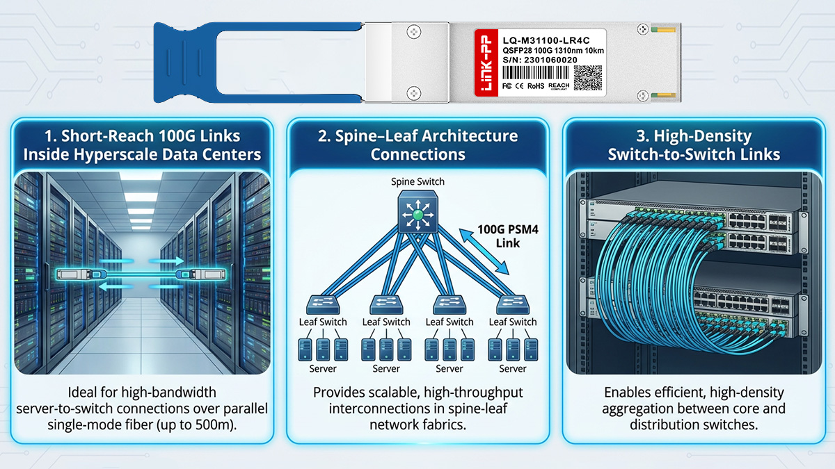
Intra-Data Center Spine–Leaf Interconnects
100G PSM4 is widely used for spine-to-leaf switch links within the same data hall where distances are predictable, fiber runs are structured, and high port density is required. In these environments, parallel single-mode trunks are often pre-installed between rows or network pods.
PSM4 fits well in leaf-spine architectures because:
-
Link distances typically remain under 2km
-
High port counts demand lower cost per 100G port
-
MPO trunk cabling simplifies large-scale deployment
-
Parallel optics align with structured cabling design
| Scenario |
Distance |
Why PSM4 Fits |
| Leaf–spine links |
≤300m |
High density + short reach |
| Row-to-row switching |
≤2km |
MPO trunk reuse |
| Fabric interconnect |
≤2km |
Predictable paths |
In these cases, PSM4 provides a straightforward way to scale bandwidth without introducing wavelength multiplexing complexity.
Hyperscale and Cloud Data Centers
100G PSM4 is particularly common in hyperscale environments where thousands of short-reach 100G links operate simultaneously and minimizing cost per port is critical. Large cloud providers often deploy parallel fiber infrastructure from the outset, making PSM4 a natural fit.
It is typically chosen when:
-
Parallel SMF trunks are already installed
-
Massive east–west traffic dominates
-
Switch density is very high
-
Optical cost scaling matters
Compared with duplex-fiber 100G optics, PSM4 often reduces total optical cost in these large deployments, even though it uses more fibers.
AI and High-Performance Computing Clusters
AI and HPC environments generate heavy east–west traffic between compute nodes, storage systems, and GPU clusters. These deployments often prioritize predictable latency, structured cabling, and high bandwidth density within a single facility.
PSM4 is suitable for:
-
GPU cluster interconnects
-
Storage fabric links
-
High-throughput compute pods
-
Rack-scale parallel architectures
Because these networks are typically built with parallel fiber from the beginning, PSM4 integrates naturally into the cabling model.
Migration from 40G Parallel Fiber Architectures
100G PSM4 is often used when upgrading data centers that previously deployed 40G SR4 or parallel single-mode trunk systems. In such environments, MPO cabling is already in place, allowing operators to scale from 40G to 100G without redesigning the physical layer.
Common migration scenarios include:
-
Replacing 40G SR4 with 100G PSM4
-
Reusing MPO trunk infrastructure
-
Upgrading spine switches to 100G
-
Maintaining parallel cabling topology
This reuse of existing fiber infrastructure can significantly reduce upgrade cost and complexity.
When 100G PSM4 Is Not Ideal
100G PSM4 is not the best choice when link distance exceeds 2km or when only duplex fiber is available. In those cases, wavelength-multiplexed solutions are typically more appropriate.
Avoid PSM4 when:
-
Links exceed 2km
-
Fiber count must be minimized
-
Inter-building connectivity is required
-
Only LC duplex fiber is installed
Understanding these boundaries helps ensure PSM4 is deployed where it delivers the most value: short-reach, structured, high-density data center networks built around parallel single-mode fiber.
🔰 Fiber Infrastructure Requirements for 100G PSM4
100G PSM4 requires parallel single-mode fiber infrastructure using MPO connectivity and eight active fibers per link, making it best suited for data centers that already deploy structured MPO trunk cabling for short-reach connections up to 2km. Proper fiber planning is critical because PSM4's performance and scalability depend directly on cabling topology, polarity, and connector management.
Unlike duplex-fiber 100G optics, PSM4 does not multiplex wavelengths onto a single fiber pair. Instead, it relies on multiple parallel lanes, which means the physical fiber design must be planned from the start or validated before deployment.
Fiber Type and Distance Support
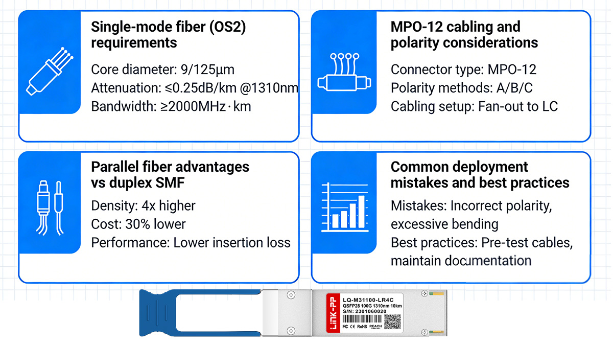
100G PSM4 is designed for transmission over OS2 single-mode fiber and supports link distances up to 2km inside a data center. It is not intended for multimode fiber or long-haul inter-building links.
PSM4 should be used when short-reach single-mode links are required and structured parallel fiber is available.
| Fiber Type |
Supported |
Maximum Reach |
Typical Use |
| OS2 SMF |
Yes |
2km |
Intra-data-center |
| OM3/OM4 MMF |
No |
— |
Not applicable |
| Duplex SMF only |
Limited |
— |
Not ideal |
Although PSM4 uses single-mode fiber, its reach is intentionally limited to short distances to maintain stable performance and predictable power budgets across parallel lanes.
MPO Connector and Fiber Count
100G PSM4 uses an MPO-12 connector with eight active fibers (4 transmit + 4 receive). The remaining four fibers in the connector are unused. This parallel design allows simultaneous multi-lane transmission but requires correct polarity and trunk mapping.
PSM4 infrastructure must support:
| Interface |
Connector |
Active Fibers |
Cabling Style |
| 100G PSM4 |
MPO-12 |
8 |
Parallel SMF |
| 100G DR4 |
MPO-12 |
8 |
Parallel SMF |
| 100G CWDM4 |
LC duplex |
2 |
Duplex SMF |
Because of the higher fiber count, PSM4 is most efficient in environments where MPO trunks are already standardized across rows or pods.
Polarity and Cabling Design Considerations
Correct MPO polarity is essential for PSM4 deployment because transmit and receive lanes must align precisely across all eight active fibers. Misconfigured polarity can prevent links from establishing or reduce performance across individual lanes.
Before deployment, operators should verify:
-
MPO polarity type (Type A/B/C)
-
Patch panel mapping
-
Fiber continuity across trunks
-
Lane alignment across switches
Recommended practices include:
-
Pre-testing trunk cables
-
Using consistent polarity standards
-
Labeling MPO paths clearly
-
Avoiding unnecessary conversions
A structured cabling approach ensures predictable link performance and easier scaling as port counts increase.
Structured Cabling and Scalability
PSM4 is most effective in data centers designed with parallel fiber trunks connecting rows, pods, or network zones. In these environments, MPO-based structured cabling enables scalable deployment of 100G links without frequent recabling.
PSM4 scales well when:
-
MPO trunks are pre-installed
-
Switch fabrics expand horizontally
-
Port density is high
-
Distances remain within 2km
However, if a facility relies primarily on duplex LC fiber, deploying PSM4 may require significant recabling. In those cases, duplex-fiber 100G optics may be more practical.
Fiber Management and Operational Best Practices
Maintaining stable PSM4 links requires careful fiber management due to the number of active fibers and sensitivity of MPO connectors. Cleanliness and proper handling directly affect optical performance.
Best practices include:
-
Inspecting and cleaning MPO connectors before use
-
Monitoring optical power per lane
-
Maintaining bend radius in trunk cables
-
Using structured patch panels
-
Documenting fiber routing
By ensuring correct fiber infrastructure from the beginning, operators can fully leverage the cost and scalability benefits of 100G PSM4 in high-density data center networks.
🔰 Practical Deployment Solutions Using 100G PSM4
100G PSM4 is most effective when deployed in short-reach data center environments that already use MPO-based single-mode fiber infrastructure and require scalable, cost-efficient 100GbE connectivity. Practical deployment decisions typically revolve around whether existing cabling can be reused, how port density will scale, and whether parallel optics align with long-term network architecture.
Rather than treating PSM4 as a universal 100G solution, network designers should evaluate it as a targeted option for specific scenarios where parallel fiber and predictable link distances make it operationally efficient.
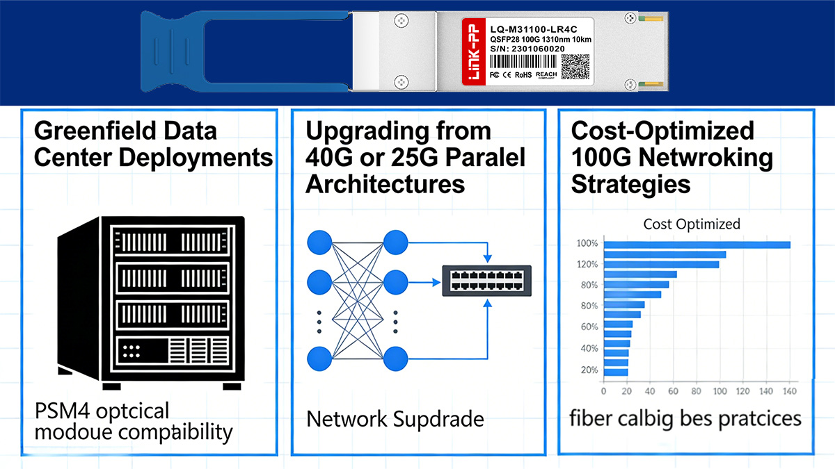
Greenfield Data Center Deployments
100G PSM4 is a strong choice in new data centers designed with parallel single-mode MPO trunk cabling from the outset. When fiber infrastructure is planned for high-density switching fabrics, PSM4 can provide consistent short-reach 100GbE connectivity with lower per-port optical cost.
PSM4 fits well in greenfield deployments when:
-
MPO-based single-mode trunks are installed between rows
-
Leaf–spine links remain within 2km
-
High port density is required across switching layers
-
Optical cost scaling is a priority
| Deployment Type |
Fiber Design |
Why PSM4 Works |
| Hyperscale DC |
MPO SMF trunks |
Cost-efficient scaling |
| Enterprise DC |
Structured cabling |
Predictable short reach |
| AI clusters |
Parallel fiber |
High bandwidth density |
In these environments, parallel optics simplify consistent cabling layouts across multiple network layers.
Upgrading from 40G or Parallel Fiber Architectures
100G PSM4 is often deployed when upgrading data centers that previously used 40G SR4 or other parallel-fiber architectures. Because both 40G and PSM4 rely on MPO-based structured cabling, many existing trunk systems can be reused without redesigning the physical layer.
PSM4 is a practical upgrade path when:
-
MPO trunk infrastructure already exists
-
Link distances remain short
-
Spine switches are moving to 100G
-
Fiber plant redesign should be avoided
| Existing Infrastructure |
Upgrade Path |
| 40G SR4 MMF trunks |
Replace with SMF + PSM4 |
| 40G PSM4 SMF trunks |
Direct 100G PSM4 upgrade |
| MPO backbone |
Reuse for 100G links |
Reusing parallel cabling reduces downtime, lowers upgrade cost, and keeps network topology consistent.
Cost-Optimized 100G Deployment Strategies
100G PSM4 is often selected in large-scale deployments where minimizing cost per 100G port is more important than minimizing fiber count. In environments with thousands of short-reach links, the simplicity of parallel optics can reduce total optical expenditure compared with wavelength-multiplexed alternatives.
Choose PSM4 when:
-
Parallel fiber is available
-
Link distances are short
-
Optical budget per port matters
-
High-density switching is required
Avoid PSM4 when:
-
Fiber count must be minimized
-
Links exceed 2km
-
Only duplex fiber is installed
-
Inter-building connectivity is required
This decision framework helps ensure PSM4 is used where it delivers operational and economic value.
High-Density Spine–Leaf Fabrics
PSM4 supports high port density in spine–leaf architectures where dozens of 100G links run between switches within the same facility. Because all links share similar distances and cabling structures, parallel optics can simplify planning and maintenance.
In these fabrics, PSM4 enables:
-
Uniform cabling across rows
-
Predictable optical budgets
-
Scalable east–west bandwidth
-
Consistent switch port utilization
| Fabric Layer |
Typical Distance |
PSM4 Suitability |
| Leaf–spine |
50–300m |
Excellent |
| Spine–core |
≤2km |
Suitable |
| Inter-building |
>2km |
Not recommended |
PSM4 performs best when link distances remain predictable and within its designed optical budget.
Operational Deployment Considerations
Successful PSM4 deployment requires careful planning around fiber mapping, polarity, and port layout. Because each link uses multiple fibers, cable management and documentation become especially important in dense environments.
Before deploying PSM4, operators should:
-
Verify MPO polarity across trunks
-
Confirm fiber continuity
-
Plan structured patch panel layouts
-
Monitor per-lane optical power
-
Standardize cabling across racks
These practices help ensure reliable performance and simplify troubleshooting as the network scales.
🔰 100G PSM4 vs Other 100G Optical Interfaces
100G PSM4 is the best choice for ≤2km intra-data-center links where parallel single-mode MPO fiber is already deployed and minimizing cost per 100G port is a priority. Other 100G interfaces such as CWDM4, DR4, and SR4 are better suited for duplex-fiber environments, longer distances, or multimode infrastructures.
Choosing between these interfaces is less about raw performance and more about fiber availability, link distance, and scaling strategy. Understanding how PSM4 compares with alternatives helps network designers select the most practical option for each deployment scenario.
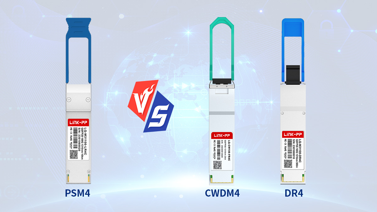
PSM4 vs CWDM4
PSM4 uses parallel single-mode fiber with eight active fibers, while CWDM4 transmits four wavelengths over a duplex LC fiber pair. PSM4 typically offers lower optical cost in MPO-based environments, whereas CWDM4 reduces fiber usage and supports longer reach up to 2km.
PSM4 is preferred when parallel fiber is available and link distances are short.
| Interface |
Fiber Count |
Reach |
Best Fit |
| 100G PSM4 |
8 SMF |
2km |
Intra-DC MPO |
| 100G CWDM4 |
2 SMF |
2km |
Campus/DCI |
CWDM4 is often selected in duplex-fiber data centers or where links extend beyond a single hall. PSM4 is more efficient when MPO trunks already exist and distances remain short.
PSM4 vs DR4
PSM4 and DR4 both use parallel single-mode fiber and MPO connectors, but DR4 supports longer reach (typically 2km with PAM4 signaling and breakout flexibility). DR4 is often used in newer architectures where 100G breakout to 4×25G or migration toward 400G ecosystems is required.
PSM4 is simpler and often lower cost for pure 100G short-reach links, while DR4 offers more flexibility in future-ready designs.
| Interface |
Signaling |
Reach |
Typical Use |
| 100G PSM4 |
4×25G NRZ |
2km |
Short-reach DC |
| 100G DR4 |
4×25G PAM4 |
2km |
Scalable fabrics |
DR4 is often favored in forward-looking data centers preparing for higher-speed transitions, while PSM4 remains common in established parallel-fiber environments.
PSM4 vs SR4
PSM4 uses single-mode fiber for up to 2km, while SR4 uses multimode fiber and typically supports shorter distances (70–150m depending on fiber type). SR4 is usually deployed inside racks or between adjacent rows, whereas PSM4 covers longer intra-data-center links.
PSM4 is chosen when single-mode fiber is required or when distances exceed multimode limits.
| Interface |
Fiber Type |
Reach |
Deployment Scope |
| 100G PSM4 |
SMF |
2km |
Row-to-row |
| 100G SR4 |
MMF |
70–150m |
Rack/row |
SR4 can be cost-effective for very short links using existing multimode fiber, but PSM4 provides greater reach and consistency across large facilities.
Decision Guidelines
PSM4 should be selected based on infrastructure and deployment goals rather than purely on specifications. It is most appropriate in structured parallel-fiber environments where link distances are predictable and cost scaling matters.
Use 100G PSM4 when:
-
MPO single-mode trunks are already installed
-
Link distances are ≤2km
-
High port density is required
-
Optical cost per port must be minimized
Choose other interfaces when:
-
Only duplex fiber is available
-
Distances exceed 2km
-
Fiber count must be minimized
-
Inter-building connectivity is required
By aligning the optical interface with actual fiber infrastructure and network topology, designers can ensure that 100G PSM4 is deployed where it delivers the greatest operational and economic value.
🔰 Deployment Challenges and Considerations of 100G PSM4
100G PSM4 is straightforward to deploy in parallel single-mode environments, but it introduces specific operational challenges related to fiber count, MPO management, and short-reach design limits. Successful deployment depends on validating fiber infrastructure, ensuring correct polarity, and aligning PSM4 with long-term network scalability plans.
Although PSM4 simplifies optical design internally, its parallel architecture requires careful planning at the physical layer. The following considerations help avoid common deployment issues.
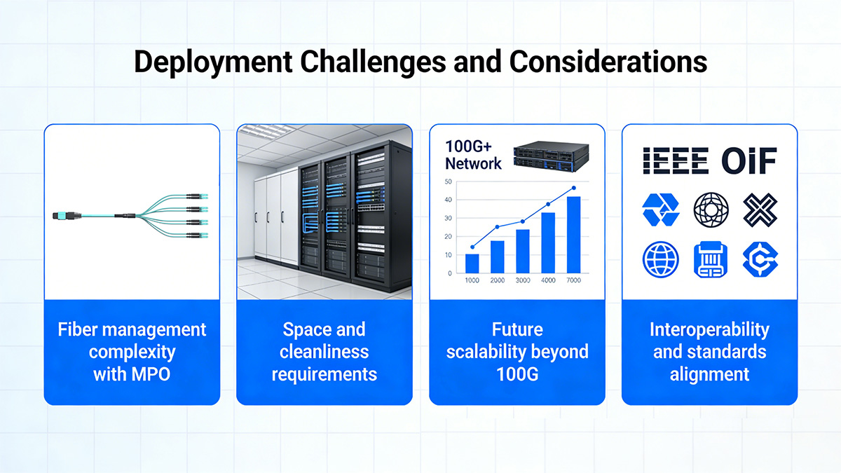
MPO Fiber Management Complexity
100G PSM4 uses eight active fibers per link, which increases cabling density and requires disciplined fiber management compared with duplex-fiber 100G optics. Without structured routing and labeling, troubleshooting can become difficult in large-scale deployments.
PSM4 requires more fiber but remains manageable when structured cabling is implemented correctly.
| Interface |
Active Fibers |
Management Complexity |
| 100G PSM4 |
8 |
Moderate |
| 100G DR4 |
8 |
Moderate |
| 100G CWDM4 |
2 |
Low |
Best practices include:
-
Using structured MPO trunk cabling
-
Labeling patch panels and trunks clearly
-
Maintaining consistent routing paths
-
Avoiding excessive patch conversions
When these practices are followed, parallel fiber complexity becomes predictable and scalable.
Polarity and Lane Alignment
Correct MPO polarity is critical because all four transmit and four receive lanes must align properly between switches. A single polarity mismatch can prevent link establishment or cause lane-level performance issues.
Before deployment, operators should verify:
-
MPO polarity type across trunks
-
Patch panel mapping consistency
-
End-to-end lane alignment
-
Fiber continuity
Testing trunks before installation reduces troubleshooting time and prevents link failures in dense fabrics.
Distance and Use-Case Limitations
PSM4 is designed specifically for short-reach data center links and should not be used beyond its intended distance range. Deploying PSM4 in scenarios that exceed 2km or require inter-building connectivity can result in unstable links or insufficient optical budget.
PSM4 is appropriate only when link distances remain within its designed range.
| Link Type |
Distance |
PSM4 Suitability |
| Same row |
≤100m |
Ideal |
| Row-to-row |
≤2km |
Suitable |
| Campus/DCI |
>2km |
Not recommended |
If longer reach is required, duplex-fiber 100G optics such as CWDM4 or LR-based modules are typically more appropriate.
Scalability and Future Network Planning
While PSM4 works well for current 100GbE deployments, network planners must consider how the fiber infrastructure will evolve toward higher speeds such as 200G or 400G. Parallel fiber designs can scale effectively, but only if the cabling system is standardized and documented.
PSM4 aligns well with future scaling when:
-
MPO trunk systems are standardized
-
Parallel cabling is maintained consistently
-
Switch upgrades follow similar architecture
-
Fiber pathways are documented
However, if a network plans to transition primarily to duplex-fiber optics or long-reach interconnects, PSM4 may not align with long-term strategy.
Operational Monitoring and Maintenance
Parallel optics require consistent monitoring across multiple lanes to ensure stable performance. Most modern PSM4 modules provide digital diagnostics, allowing operators to track optical power, temperature, and voltage.
Operational recommendations include:
-
Monitoring per-lane optical power
-
Inspecting and cleaning MPO connectors regularly
-
Maintaining bend radius in trunk cables
-
Documenting fiber paths
-
Using standardized patching practices
Because each link uses multiple fibers, connector cleanliness and cable handling are especially important for maintaining reliable operation.
🔰 FAQs About 100G PSM4

What is 100G PSM4 mainly used for?
100G PSM4 is primarily used for ≤2km intra-data-center 100GbE links where parallel single-mode MPO fiber is already deployed and high port density is required.
How many fibers does 100G PSM4 require?
100G PSM4 uses 8 active single-mode fibers (4 transmit + 4 receive) within an MPO-12 connector for a single 100Gbps link.
What is the maximum distance of 100G PSM4?
100G PSM4 typically supports up to 2km over OS2 single-mode fiber in controlled data center environments.
When should you choose PSM4 over CWDM4?
Choose 100G PSM4 when MPO-based parallel SMF is available and link distances are ≤2km; choose CWDM4 when only duplex fiber is installed or reach up to 2km is required.
Can 100G PSM4 run over multimode fiber?
No. 100G PSM4 is designed specifically for single-mode fiber and is not compatible with multimode fiber infrastructure.
Is 100G PSM4 suitable for inter-building links?
No. 100G PSM4 is intended for short-reach intra-data-center connections and is not recommended for campus or inter-building links beyond 2km.
Does 100G PSM4 support breakout connections?
Standard 100G PSM4 is typically used for direct 100G links and does not commonly support breakout to multiple lower-speed interfaces.
🔰 Conclusion
100G PSM4 is a cost-efficient and scalable 100GbE solution for short-reach data center links where parallel single-mode MPO fiber is already deployed and link distances remain within 2km. It enables high-density spine–leaf fabrics, supports predictable intra-data-center connectivity, and helps control cost per 100G port in environments built around structured parallel cabling.
Its real value lies in alignment with infrastructure. When MPO-based single-mode trunks are available and most links stay inside a single facility, 100G PSM4 provides a straightforward path to scale bandwidth without adding the complexity of wavelength multiplexing. In contrast, duplex-fiber or longer-distance scenarios are typically better served by CWDM4, DR4, or LR-class optics. Evaluating fiber layout, distance, and future scaling plans ensures PSM4 is deployed where it delivers the greatest operational and economic benefit.
For organizations planning or expanding short-reach 100G networks, choosing interoperable and field-tested 100G PSM4 modules from a reliable supplier can simplify deployment and reduce risk across multi-vendor environments. To explore compatible and deployment-ready 100G PSM4 solutions, visit the LINK-PP Official Store for detailed specifications, application guidance, and product availability.